

- 00000018WIA3084B770GYZ
- id_400217161.5
- Mar 24, 2022 5:16:08 PM
Navigator: acquire a coronary artery scan
About this task
Use these steps to acquire a Navigator free-breathing, coronary artery imaging acquisition. A phased array coil is recommended, typically the Cardiac or Torso Array coil.
Review the description of the respiratory signal on the Navigator Monitor. Note that Threshold and Acceptance Window are also adjustable from the Navigator Monitor during scan.
The Navigator Monitor window opens when the navigator sequence starts scanning. This window remains open for the entire scan. Click Done to close it and click Navigator at the bottom of the Scan Operations area to re-open it.
When the Navigator Monitor window opens, it takes the system time to obtain a baseline as the patient’s breathing and diaphragm movements are monitored. The time during which the baseline data is gathered can be as long as 30 to 45 seconds. For a patient with an erratic heart rate or an unusual breathing pattern, this baseline time may be longer.
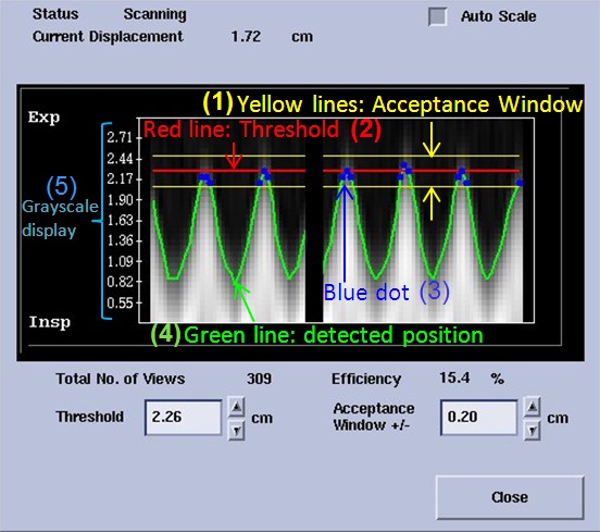
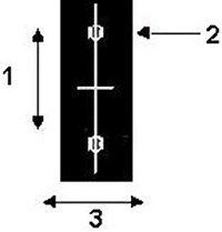
| Number | Description |
|---|---|
| 1 | The signal is only detected if it is within the Acceptance window or between the two yellow lines. Change the value to increase or decrease the distance between the yellow lines. |
| 2 | The Navigator threshold is represented by the red line. As you change the Threshold value you move the Acceptance Window up or down. |
| 3 | The blue dot represents acquired signals. Blue dots only occur between the yellow lines. If there is no green line between the yellow Acceptance Window, then no respiratory signal is detected. |
| 4 | The green line represents the respiratory waveform. |
| 5 | The Grayscale display shows real time navigator signal at the navigator tracker. |
- Start a scan session.
- Select a protocol from your Site or GE library that has a real time localizer and a 3D FGRE or 3D FIESTA with Navigator and Cardiac Gating as selected Imaging Options.
- Acquire localizer images with Real Time imaging.
- From the Workflow Manager, select a Real Time series with i/Drive Pro Plus and click Setup.
- Make any changes as needed, and then click to initiate the Real Time acquisition.
- Change the Slice Thickness to 8.
- Select the coronal Home image.
- Click Define Scout.
- Click Draw Line and position the vertical line cursor over the right diaphragm.
- Click Save Image when the diaphragm is in the most superior location (expiration).
- Click Draw Line to turn the line tool off.
- Select the coronal Home image.
- Click Step and position the cursor so that the arrow is pointing either towards or away from you.
- Click until you see a good heart image.
- Click Save Image to capture several coronal images for positioning the 3D volume.
- From the Workflow Manager, select the Navigator series and click Setup.
- Make scan parameter adjustments, as needed.
- Click the Navigator tab and make adjustments as needed.
- Slab Tracking turns on a rigid motion correction process for Navigator Gating and Inhance 3D Inflow IR scans.
- Acceptance Window is the range for data acquisition. Image data is only acquired when the signal is detected within this range. It can be changed from the Navigator Monitor window during the scan.
- Navigator Prescan Time defines the duration of the Navigator prescan.
- Navigator Type is used to suppress black bands. Black suppression bands are seen in images when 90-180 navigator type is used. No suppression bands are seen in the image when cylindrical navigator type is used.
- The option does not appear with coronary imaging on 3.0T systems, which automatically use 90-180 navigator type.
- The option does not appear with body imaging, which automatically use cylindrical navigator type.
- This option is only available with coronary artery imaging on a 1.5T system if the Imaging Option IR Prep is not selected.
Figure 2. Suppression bands 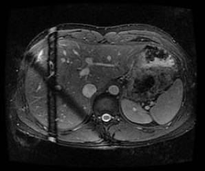
- Graphically prescribe the Navigator scan locations and tracker.
- Click the
 .
. - Deposit the 3D slab over the area of interest.
Figure 3. 3D Navigator slab 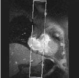
- Display an image on which the liver-lung edge can be visualized.
- From the Graphic Rx Toolbar, click Tracker and then click to deposit the Navigator tracker on the image.
Figure 4. Navigator tracker position 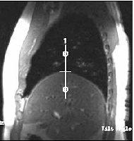
- Click the
| Number | Description |
|---|---|
| 1 | Tracker length |
| 2 | Rotate handle |
| 3 | Tracker thickness |
Step-by-step instructions
- Place the center tick-mark of the tracker line at the top of right hemi-diaphragm and liver dome. Center the graphic tracker line at the diaphragm and lung interface.
- In the Tracker Length text box, type 120.
- In the Tracker Thickness text box, type 20.
- If needed, re-adjust the position of the Navigator tracker.
- From the Workflow Manager, click to start the Navigator acquisition.
- Breathing control instructions
- Give the patient breathing instructions before the scan. A shallow, relaxed and consistent breathing pattern results in better image quality and a shorter scan time.
- The respiratory drift can be minimized by wrapping a Velcro band (such as an MRI-compatible orthopedic brace) across patient’s abdominal region, below the rib cage.
- Monitor the breathing pattern with a bellow. Wait until the breathing pattern becomes consistent to begin the scan.
- Breathing control instructions
- Monitor the Navigator pulse.
- For details about the navigator waveform, the causes and corrective actions, see Navigator: considerations and troubleshooting tips.
- When you begin the Navigator acquisition, the Navigator Monitor screen opens. Your MR system determines and displays a baseline respiratory cycle. The status area of the Navigator Monitor window indicates the baseline is being acquired. As the status of the scan changes, the status area updates to reflect the current status of the scan.
- When the Navigator window opens, it takes the system time to obtain a baseline as the patient’s breathing and diaphragm movement are monitored. The time during which the baseline data is gathered can be set by Navigator Prescan Time in Navigator tab.
- When baseline data is gathered, the Acceptance Window and Threshold fields are unavailable.
- Navigator scan time uses the following formula: scan time = [(phase value ÷ number of overscans) × (60 sec ÷ heart rate)/efficiency number].
- If the scan efficiency is higher than 40%, reduce the navigator window to +/- 1 mm so the scan efficiency falls between 30%-40% range. This avoids introducing too much motion while the scan is in progress, since the non-liner relationship of the motion between the heart and the diaphragm cannot be corrected effectively with the linear correction factor used in slice tracking.
- View the baseline respiratory waveform and phase displacement of the Navigator tracker.
- Adjust the displacement of the Navigator tracker, if necessary.
- Select Auto Scale as needed.
- When Auto Scale is off, the entire navigator signal is displayed.
- When Auto Scale is on, the respiratory waveform and acceptance window are magnified.
- If there is a gap between the green line and the diaphragm position, if needed, turn off Auto Scale to see the entire grayscale.
Figure 6. Gap between green line and diaphragm position 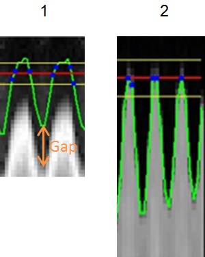
Table 3. Image legend Number Description 1 Green line does not match with diaphragm position. 2 Good match between green line and diaphragm position.
- If there is a gap between the green line and the diaphragm position, if needed, turn off Auto Scale to see the entire grayscale.
- In the Threshold text box, type a value to shift the threshold displacement.
- Immediately after the Navigator calibration period, adjust the navigator threshold so that the end expiration point falls on or above the red line.
- Threshold can be changed before the beginning of each slab if the end expiration level changes over time. For optimum image quality, minimize the changes in navigator threshold values during the acquisition of each slab. If the patient’s end expiration level drifts outside the navigator window, wait 3-5 breathing cycles for it to stabilize before changing the threshold.
- In the Acceptance Window text box, type a value to widen or narrow the acceptance window. Increasing the acceptance improves data acquisition time, but degrades the images quality due to more motion contamination in the data acquisition window.
- Open and close the Navigator window as needed.
- From the Workflow Manager, click to start the Navigator acquisition.
- Click Close to close the Navigator Monitor window.
- Click Navigator at the bottom of the Scan Operations area to re-open it.