

- 00000018WIA30322970GYZ
- id_400245331.4
- Aug 19, 2022 12:37:38 PM
Multi-phase: parameter selections
About this task
- Interleave mode to temporally resolve time course studies.
- Sequential mode for joint motion studies of the knee, TMJ, and wrist.
Use the following procedure to complete the Multi-Phase scan parameters on the Multi-Phase tab.
Step-by-step instructions
- If available and required for your applications, select Variable Delays. It's availability is dependent on the selected PSD. If it is not available, then you are unable to enter specific times for each phase.
Figure 1. Variable Delays display area 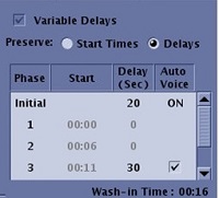
- Click Variable Delays option box.
- Place the cursor in either the Start or Delay (Sec) text fields and type and enter a new time.
- Each time you enter a phase delay, the system recomputes and updates the corresponding and subsequent phase start times.
- When Smart Prep or Fluoro Trigger Imaging Option is selected with Multi-Phase and Variable Delays, the Image Acquisition Delay User CV and the first phase delay have the same value. If either value is changed, the other value is automatically adjusted.
- When Variable Delay is selected, the Initial row represents the delay time that occurs before the first phase and after the mask phase. The time delay is the time from clicking Scan to the start of the acquisition of the first phase, post mask.
- The mask phase is not represented in the Variable Delay display and is not included in the Total Time. You can change the delay time for the initial phase and it will not change the Total Time. Change the delay time for any of the other phases and the Total Time updates.
- Each time you enter a phase delay, the system recomputes and updates the corresponding and subsequent phase start times.
- When Variable Delays are selected, Phase Acquisition Order and Delay After Acquisition are not available.
- Each time you enter a phase delay, the system recomputes and updates the corresponding and subsequent phase start times.
- There are two Preserve options that determine if the start time is kept or the delay time is kept for each phase when the scan time is changed.
- Start Times results in the inter-phase delay time column as a non-editable field.
- Delays results in the inter-phase delay and start time as an editable field.
- On the Multi-phase screen, an * appears next to a Start time or Delay if it is unable to preserve it based on the selected Preserve mode. In addition, a message appears in the Scan Parameter message area.
Figure 2. * on Start time or Delay 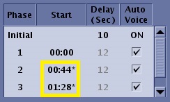
- On the Multi-phase screen, an * appears next to a Start time or Delay if it is unable to preserve it based on the selected Preserve mode. In addition, a message appears in the Scan Parameter message area.
- Select a Phase Acquisition Order.
Figure 3. Acquisition order 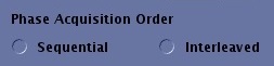
- The following selections apply to Multi-phase SSFSE sequences:
- Select Sequential to acquire imaged in a phase-then-slice order where all the phases at the first slice location (pass 1) are collected before moving to the second location (pass 2). Sequential phase acquisition order may depict motion (of the bowel, for example) more clearly, because all phases for a single slice are collected sequentially in time, one after the other. In general, Sequential results in higher temporal resolution and lower SNR, although SNR may be improved by increasing the TR value.
- Select Interleaved to acquire images in a slice-then-phase order where the first phase at each location (pass 1) is collected and then the second phase at each location (pass 2) is collected, and so on. Interleaved phase acquisition order produces higher SNR, because it gives the signal in a particular slice more time to recover before subsequent phases are collected.
- The following selections apply to Multi-phase SSFSE sequences:
- Type a Delay After Acq value, in seconds, for each phase delay after the end of the scan for the corresponding phase.
Figure 4. Delay After Acquisition 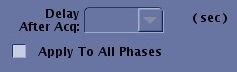
- If you want all phases to have the same delay, select Apply to All Phases.
- Times available are the minimum value to 20 seconds. The value is rounded to 1 second.
- Locs before Pause may be selected instead of programming the delay after acquisition. If so, select the minimum delay after acquisition.
- If you want all phases to have the same delay, select Apply to All Phases.
- Select Mask Phase to create a mask phase and select Pause after Mask to pause the scan after the Mask Phase.
Figure 5. Mask Phase and Pause after Mask 
- Make desired Auto Subtract selections.
Figure 6. Auto Subtract 
- The Series to Subtract list appears when Auto Subtract is selected.
Figure 7. Series to Subtract list 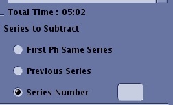
- Select one of the Series to Subtract options:
- Select First Ph Same Series if all phases (pre and post contrast) are acquired within the same series.
- Select Previous Series to enable subtraction between the current series images and the previous (last scanned) series images. Select only if the previous series was the series from which you want to subtract the contrast-enhanced images. The series you are subtracting from needs to have parameters that match (i.e., the Graphic Rx parameters must match).
- Select Series Number if you do not want the subtraction to be done with the previous series; you can explicitly type in the series number you wish to do the subtraction from. The series you are subtracting from needs to have parameters that match (i.e., the Graphic Rx parameters must match).
- Select one of the Series to Subtract options:
- The Series to Subtract list appears when Auto Subtract is selected.
- Select Series per Phase to specify the images produced are placed into one series per phase instead of into a single series.
Figure 8. Series per Phase 
- The maximum # of phases is 99. When off, all images produced by a given series are placed into a single series. This option is only available if Variable Delays is selected.
Figure 9. Patient List displays series 400 to 405, which were acquired with Series per Phase 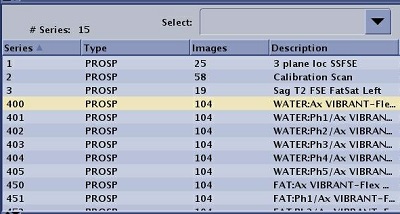
- The maximum # of phases is 99. When off, all images produced by a given series are placed into a single series. This option is only available if Variable Delays is selected.
- Review the visual multi-phase display.
Figure 10. Multi-phase visual display 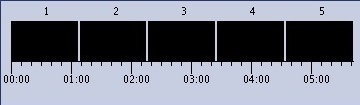
- The visual display illustrates the acquisition time line. The time line diagram does not include the mask phase.
Results
- Images acquired at a single location with multiple phases may appear shifted upon display. This is most noticeable when these images are loaded into a paging-loop mode.
- When a Multi-Phase (variable delays) series is selected, the Scan Operation's appearance and behavior is the same as for other types of scan, except for the following.
- When a Multi-Phase series is downloaded, the Scan button is disabled until the series has been prepped. Since prescan time is unknown, if you click Start before Prep, there is no guarantee that prescan will complete before the first phase delay elapses.
- When the scanner is in a waiting state, it is indicated on the status bar.
- For a Multi-Phase series, an additional toggle button is displayed allowing you to switch to Manual Mode and back to Normal Mode. This button is available when DE Prepared is selected as an Imaging Option, until the end of the Multi-Phase sequence. In Manual Mode, the Scan button is available as soon as the delay starts, and until you have pressed it to confirm the next phase start.
Figure 11. Multi Phase variable delays Scan Operations area 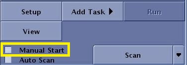
- The scan time displayed in the Scan Operation area is the total time (from the start of the first phase scan to the end of the last phase scan). When Multi-Phase (variable delays) is selected, the scan progress display area displays the following information.
Figure 12. Scan Time for Multi-Phase 
- Current phase and total number of phases (blank during initial delay).
- Delay or Scan time count down for the current phase (label shall be “Delay time” during delay and “Scan time” while scanning)
- Total scan time count down.
- In calculating the scan time, consider the following:
- When the system is entering a waiting state or when the scan is started early with the Start button, the total time is re-adjusted (i.e. set to the time required to scan the remaining phases).
- When the scan is paused during a scan, the scan time and total time count down are interrupted and continue when the scan is resumed.
- When the scanner is waiting and in Manual Mode, and the prescribed delay is elapsed, both delay time and total time count down are interrupted and continue when the next phase scan is started.
- For additional (manual) phases scanned after the Multi-Phase (variable delays) sequence is completed, only the current phase and scan time are displayed (not the delay time, nor the total time)
- The actual phase start time that is annotated on the image is the time when the phase scan starts, in seconds, expressed relative to the reference time: <Total # of Scan Loc>/<Total Scan Time >
Figure 13. Scan phase annotated in upper left corner 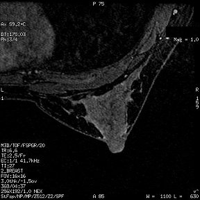
- The scan time displayed in the Scan Operation area is the total time (from the start of the first phase scan to the end of the last phase scan). When Multi-Phase (variable delays) is selected, the scan progress display area displays the following information.