- 00000018WIA30ED1970GYZ
- id_400246971.4
- Aug 18, 2022 12:40:58 PM
ARC
ARC is a data-driven parallel imaging technique that synthesizes missing data from neighboring source data in all three imaging dimensions: slice, phase and frequency. Fewer calibration lines are required and reconstruction accuracy and speed is improved resulting in highly accelerated MR data acquisition with improved image quality and reduced artifacts.
ARC is auto-calibrating, which means that it requires no coil sensitivity map and is therefore less sensitive to motion artifacts that would occur between the calibration and accelerated scan. It can be used with tight FOVs that are smaller than the anatomy being imaged and thus allow high resolution imaging.
Since there is no calibration scan required and fewer artifacts, the ARC exam is typically shorter in comparison to other parallel imaging techniques.
ARC details
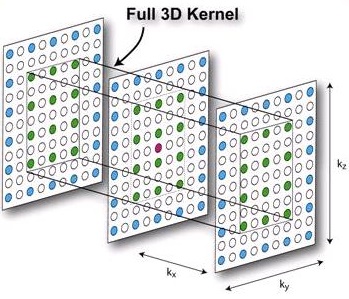
ARC uses a full 3D kernel to synthesize missing target data (pink data point) from neighboring source data (green data points), therefore taking full advantage of available information along all three dimensions.
Considerations
- Position the patient and select an ARC compatible PSD or Application and coil. ARC is not available from the Imaging Option screen if the selected PSD, Application or coil do not support it.
- From the Acceleration tab, select a Phase or Slice acceleration factor.
Figure 4. Acceleration tab 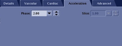
- 2D PSDs only support Phase acceleration; hence Slice Acceleration is not selectable.
- 3D PSDs support both Phase and Slice ARC acceleration but one of the acceleration controls may be locked due to application specific needs.
- If both Phase and Slice accelerations are available, preferably select Phase acceleration first.
- Default acceleration values are Phase = 2 (or coil limit if smaller) and Slice = 1 if the selected coil is capable of Phase acceleration for the selected Phase direction. Otherwise, default acceleration values are Phase = 1 and Slice = 2 (or coil limit if smaller) assuming coil has slice acceleration capability.
- Setting Acceleration Phase = 1 turns off ARC.
- You may need to adjust the Frequency Direction for optimum parallel imaging direction. For example, breast coils do not have anterior elements that support ARC acceleration in the A/P direction. Therefore, for Axial Breast imaging, place the phase direction along R/L.
- The Phase and Slice acceleration capabilities change based on the selected coil, Frequency direction, an d scan plane selection. It is possible to have both Phase and Slice Acceleration entries grayed out due to lack of acceleration support in the selected direction. Set acceleration values once coil, scan plane, and Frequency Direction are finalized.
- You can enter values that are not populated in the menus. Values you enter are automatically rounded to the closest allowed value.
- The last entry in the menu is the maximum allowed Acceleration factor. An error message is displayed if a larger value is entered.
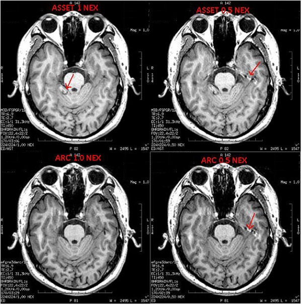
- Acceleration reduces SNR and potentially introduces parallel imaging artifacts such as aliasing and noise amplification. Be prudent when using it. Phase wrap artifacts are projected to the FOV edge and not to the center of the FOV.
- If artifacts are seen in a particular direction (Phase or Slice), consider reducing or turning off acceleration in that direction.
- Acceleration may not always result in scan time reduction but rather it might reduce image blur or increase the maximum number of slices per TR.
- When acquiring a BRAVO scan, acceleration in the slice direction may lead to suboptimal SNR and CNR and it results in less scan time reduction than acceleration in the phase direction.
- Phase and slice accelerations may not result in the same amount of scan time reduction.
- To ensure consistent image quality when using parallel imaging, be sure that the scan coverage is a good match with coil coverage.
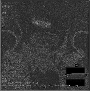
Figure 5. Example of: Coronal reformat of axial LAVA-Flex scan with ARC Phase = 2 (A/P). Coil position is well matched with scan coverage in Accelerated A/P direction 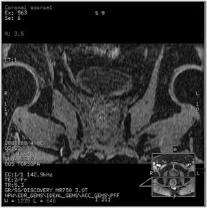
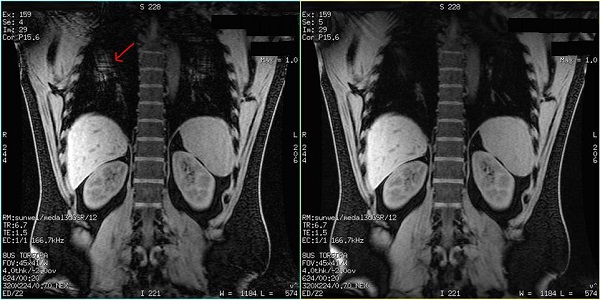
Figure 6. Example of: Coronal reformat of sagittal LAVA-Flex scan with ARC Slice = 2 (R/L). Coil coverage in R/L is much larger than the scan coverage in R/L direction resulting in noise amplification due to parallel imaging technique.