MAVRIC SL (Multi-Acquisition with Variable ResonanceImage Combination SeLective) Metal Analysis scan is sold under the marketing name of HyperMAVRIC SL. HyperMAVRIC SL is a feature that enables a 40% shorter scan time by automatically tailoring the acquisition to the patient's implant.
Indications for use
MAVRIC SL is a combination of an acquisition technique and post-processing software intended for use on GE 1.5T and 3.0T MR systems. MAVRIC SL is suitable for use on all patients cleared for MR exams. MAVRIC SL helps reduce artifacts caused by the presence of metal in both in-plane and through-plane dimensions compared to conventional MR imaging techniques. Thus, MAVRIC SL allows visualizing more tissue in the vicinity of MR Conditional implanted metal instrumentation. When interpreted by a trained physician, images generated by MAVRIC SL provide information that can be useful in determining a diagnosis.
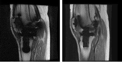
Figure 1. 1.5T Knee image acquired with 2D FSE on left and MAVRIC SL on right
About this task
Use these steps to acquire 3D MAVRIC SL T1, T2, PD or STIR-weighted images. MAVRIC SL uses a 3D multispectral acquisition technique to help reduce susceptibility artifacts caused by the presence for MR conditional metallic implants. Typically use MAVRIC SL to acquire hip, shoulder and knee images, where joint replacements are most common. MAVRIC SL is appropriate for any patient cleared for an MR exam.
CAUTION
Safe scanning of patients with MR Conditional devices or implants may be complex. Health care professionals that scan patients with MR Conditional devices or implants should consult the implant or device manufacturer for instructions with respect to safety guidelines.
Step-by-step instructions
Thoroughly review all safety information and considerations before starting a scan with patients that have an MR Conditional implant. Specifically, review the following topics in the safety chapter and your operator manual before the patient is brought into the scan room.
Position the patient so that the anatomy of interest is as close to isocenter as possible, to minimize shading artifacts.
Phase Correction scan parameter is not compatible with MAVRIC SL and thus when scanning off-center anatomy (e.g. shoulders), shading artifacts may occur.
If your system configuration supports RF Drive Mode, from the Details screen select the following. To view the Details screen, click the of the Scan Parameter screen
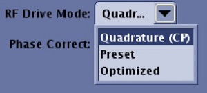
RF Drive Mode: From the RF Drive Mode menu, when scanning patients with MR Conditional metal implants or devices, select Quadrature CP. In some circumstances, it is the default and only selection. Figure 2. RF Drive Mode menu
From the Workflow Manager, click Add Task > Add Sequence.
From the Protocol screen, select a MAVRIC SL protocol from your site or GE library.
If you cannot locate a MAVRIC SL protocol in either library, then from the Imaging Options/PSD screen:
Select MAVRIC SL from the Application area. Note that the Anatomical region and coil must already be selected.
To select Metal Analysis, from the Imaging Mode menu, select Calib.
From the Family list, click Fast Spin Echo.
From the Pulse list, click Metal Analysis .
Add them to the Multi-Protocol Basket.
Click Accept.
From the Workflow Manager, select the Metal Analysis series and click Setup and then Save Rx and Scan the Metal Analysis series.
The Metal Analysis scan is a low resolution, 3D, non-selective MAVRIC scan that computes the number of bins needed for MAVRIC SL.
A Bin is essentially a 3D image acquired at a particular frequency offset from the Larmor frequency. Metal implants cause a very broad frequency (~ +/-12 kHz) distribution of the MR signal. If this broad frequency distribution is not sampled adequately, it will result in images with large artifacts. MAVRIC SL, samples this large distribution by acquiring individual images, or bins, at multiple frequency offsets. Prior to Metal Analysis scan feature, 24 bins were acquired with a separation of 1kHz between the bins to cover +/-12 kHz. This range is adequate to minimize the artifacts of most implants, including stainless steel. However, if scanning a pin or a small screw made of titanium, 24 bins are excessive. The Metal Analysis scan essentially determines the number of bins needed to adequately cover the frequency distribution created by the implant.
Once the metal analysis scan has been completed, the number of bins needed for every subsequent MAVRIC SL series is automatically updated to the minimum required for the implant.
The number of bins can be manually modified from User CV 30 if the following type-in PSD is entered from the PSD screen when 3D mode, Fast Spin Echo family and Metal Anslysis pulse are selected: mavric_cbins. The higher the number of bins, the lower the artifact. However, if only 10 bins are needed and you acquire 24 bins, the result could be noisier images with slightly higher ghosting. Reducing the number of bins lowers the minimum TR needed to acquire images and thus reduces the scan time significantly.
The Metal Analysis scan takes approximately 35 seconds to complete. Based on the implant, the investment in this additional scan has been shown to significantly reduce the scan time for subsequent MAVRIC SL series.
Metal Analysis images are annotated: M3D/Metal Analysis/flip angle.
From the Workflow Manager, select the MAVRIC SL series and click Setup.
Make scan parameter adjustments as needed. From the Scan Parameters or Details screen, select the following. To view the Details screen, click the of the Scan Parameter screen.
Image Options:
ARC when using an ARC compatible coil. ASSET is not compatible with MAVRIC SL.
EDR is defaulted to on and cannot be turned off. It can potentially increase SNR.
IR Prepared to acquire fat suppressed images.
Flow Compensation is defaulted to off.
TE : is editable. It is set to a default value of 8 ms.
Auto TR: automatically selects the optimum TR (and ETL) for the shortest scan time.
Flip angle: For safety reasons, the maximum allowed flip angle is automatically calculated based on the patient's weight and system specifications. If you reduce the flip angle, the minimum TR allowed can be reduced, which reduces the scan time. However, this may result in some degraded image quality such as ghosting, low SNR and image shading artifacts
Receiver bandwidth: It is fixed at +/- 125 kHz to reduce image distortion.
NEX: It is set to a default value of 0.5, but it can be increased to 1.
FOV: Select a FOV large enough to cover the anatomy of interest. The phase direction must be large enough to minimize image wrap.
No Phase Wrap: It is set to a default value of 1.
Intensity filter: PURE is not available with MAVRIC SL. For details, see Filter.
RF Drive Mode: From the RF Drive Mode menu, select Quadrature when scanning patients with MR Conditional metal implants or devices. In some circumstances, it is the default and only selection. RF Drive Mode only appears if your system configuration supports it.
Warning
Due to the strong magnetic field disturbance in a region containing metal, do not use the RF Drive Mode parameter: Optimized.
Warning
The tests commonly employed to determine MR Conditional implant heating safety (standard, ASTM F2182, ASTM.org), require quadrature excitation. Heating results for non-quadrature excitation (such as parallel transmit, MultiDrive, or elliptical drive) are unknown. For patients with MR Conditional implants or devices, applying Preset or Optimized RF Drive Modes may violate the MR Conditional specifications.
3D Geometric Correction: This option only corrects for distortion due to gradient non-linearity. It does not correct distortion due to susceptibility such as in metal-affected areas.
Warning
Susceptibility artifacts, such as those related to MR Conditional metal implants, will result in incorrect 3D Geometry Correction. Please carefully verify images.
If an ARC compatible coil is used, click the Acceleration tab.
The maximum Phase acceleration is set to 3 and the maximum Slice acceleration is set to 2. These numbers may exceed the acceleration capability of the coil, but it can significantly reduce the scan time.
Selecting large acceleration factors such as 3x2, may introduce additional artifacts such as low SNR and aliasing artifacts.
Graphically prescribe and position a single-slab.
If the Metal Analysis scan is not run, the single slab must have a minimum of 24 locations. If the Metal analysis scan is run, the number of locations can be lowered based on the number of bins (18, if 18 bins), with a lower end of 16.
The slab size must span the entire implant region, typically indicated by a signal void on a localizer scan.
Using MAVRIC SL images as a reference for T2Map in READY View is only available when the slice location prescription of the MAVRIC SL series and the T2Map series are exactly matched.
To set the common slice locations for both the T2Map and the MAVRIC SL series, copy/paste the graphic locations from one series to the other. For details, see Copy/paste.
Please note the following warning that applies to READY View Fusion.
Warning
READY View fusion does not function reliably if MR Conditional metal implants are present and a reference image other than the original image is used. READY View Fusion should not be applied on series if the image area includes MR Conditional metal implants. Strong B0 and B1 distortion caused by MR Conditional metal implants will cause image distortion and signal void in images. Reference images may have different level of distortion (e.g., MAVRIC SL versus non-MAVRIC SL) with functional series, and mis-registration will occur.
Saturation and shim parameters.
Saturation pulses (chemical and spatial) are NOT available due to the magnetic field changes that occur around metal implants.
It is recommended that Auto Shim be turned Off due to the magnetic field changes that occur around metal implants.
Registration in Pasting may not work with MAVRIC SL distorted images.
Warning
Do not use Pasting post process application with images that demonstrate metal implants.
When the prescription is finished, click Save Rx and Scan.
After image acquisition is finished, the reconstruction may take as long as 4 minutes to produce the final composite MAVRIC SL image.
Consider the following caution related to post-processing MAVRIC SL images on your MR, PACS, or AW systems.
CAUTION
Post processing results may be affected by the presence of MR Conditional implants. Consider the following related to post-processing MAVRIC SL images on your MR, PACS or AW systems: If an image includes susceptibility artifact, such as from MR Conditional metal implants, measurements made on the image may be incorrect due to distortion of actual physical locations.
Results
Warnings, Cautions and Considerations
CAUTION
Always base evaluations on all images in the data set and on the clinical history. Information from only a single image should not be used to evaluate a patient.
Warning
The tests commonly employed to determine MR Conditional implant heating safety (standard, ASTM F2182, ASTM.org), require quadrature excitation. Heating results for non-quadrature excitation (such as parallel transmit, MultiDrive, or elliptical drive) are unknown. For patients with MR Conditional implants or devices, applying Preset or Optimized RF Drive Modes may violate the MR Conditional specifications.
Warning
GE shall not be responsible for assessing the proper function of any device. The user of the device must consult the device manufacturer to ensure the device is MR Safe or MR Conditional. Then the user must ensure the MR Conditions are met. Finally, the user must determine what is appropriate.
Warning
The magnetic field of the MR system can cause a ferrous implant (e.g., surgical clip, cochlear implant, intracranial aneurysm clip etc.) or prosthesis to move or be displaced, resulting in serious injury. Patients and MR workers should be screened for implants and those individuals with implants should, in general, not enter the scan room. For patients and MR workers with implants that are labeled as “MR Safe” or “MR Conditional”, consult the implantable device’s labeling and the technical information about the MR system. Prostheses should be removed before scanning to help prevent injury.
MAVRIC SL follows all the safety checks and requirements, just as for any other application. Although MAVRIC SL is designed for imaging around MR Conditional metal implants, the application itself does not introduce additional safety issues. The MR operator is responsible to ensure that any implants in the patient are indeed MR Conditional and that scanning is performed in accordance with the MR system and metal implant labeling.
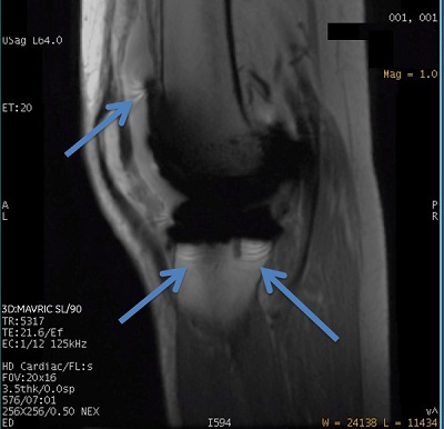
MAVRIC SL cannot completely compensate for strong magnetic field disturbances that are close to MR Conditional metal implants. It is designed to reduce but not totally eliminate the image distortion, ring or stripe like and signal void artifacts found around MR Conditional metal implants. Figure 3. Ring-like artifact in MAVRIC SL image
MAVRIC SL combines information from different spectral frequencies to generate images. Some residual blurring artifacts and slice-direction non-uniformity may be observed in the image.
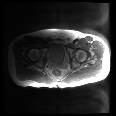
Some ghost-like artifacts may be observed in MAVRIC SL images due to the data acquisition technique. Figure 4. Ghost-like artifact in MAVRIC SL image
Auto Prescan may take longer than normal. The increased time is used to prevent signal over-range with the offsets on the transmit frequency.
CAUTION
Post processing results may be affected by the presence of MR Conditional implants. Consider the following related to post-processing MAVRIC SL images on your MR, PACS or AW systems: If an image includes susceptibility artifact, such as from MR Conditional metal implants, measurements made on the image may be incorrect due to distortion of actual physical locations.


 of the Scan Parameter screen