Use these steps to build an MR-Touch scan protocol.
Step-by-step instructions
From the header area of the screen, click the .
Click the Protocol Management tab.
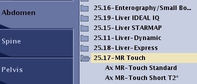
On the Protocol screen, select Abdomen > Abdomen > MR-Touch. Select the desired protocol.
Figure 1. Example of MR-Touch abdomen protocol
From the footer area of the Protocol screen, click Duplicate to duplicate and create a new protocol. If you select Duplicate, from the Properties screen, change the protocol name, filters, and other protocol properties. Click Save.
Only one protocol session can be opened at a time.
From the Protocol Edit session, select the series in the Workflow Manager you want to edit and click Setup.
Change the scan parameters, as needed.
To maintain SNR and minimize T2* effects, keep the TE as low as possible. Parameters that affect TE include: decrease bandwidth, decrease FOV, increase Frequency matrix, increase flip angle (higher flip angles can increase TE).
Keep the slice thickness to a minimum of 8 mm.
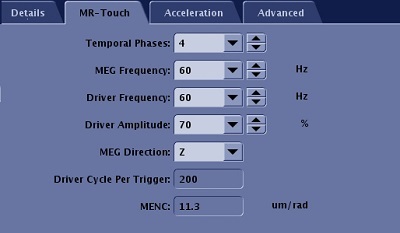
Click Details > MR-Touch and change MR-Touch parameters, as needed.
Figure 2. MR-Touch tab
Temporal Phases is the number of temporal points the MR-Touch application acquires. The phases are evenly distributed in the motion period. For optimal MR-Touch algorithm processing, use a minimum value temporal phases of 4. As the temporal phases increase, the following occurs:
phase SNR increases
the algorithm more accurately calculates the wave and stiffness
scan time increases
MEG Frequency is the frequency for the Motion Encoding Gradient, which is used to sensitize the motion. The MR-Touch sequence is a variation of a Phase-Contrast PSD. A pair of MEG gradients with mutually reversed polarities are used to convert external motion into image phases. A higher MEG frequency value leads to a shorter MEG length, and thus allows a shorter TE.
Driver Frequency refers to the frequency of the motion (wave) generated by the external MR-Touch active driver. In other words, it is the motion frequency. A higher Driver Frequency value results in a shorter wave length and better resolution at the expense of less wave penetration. The value is annotated in the DICOM as MEF.
For a liver fibrosis exam, 60 Hz is a good balance between resolution and penetration.
For an iron-loaded liver application, the signal is very low for long TE protocols due to the strong T2* effect (T2* < 10 ms). A higher MEG frequency value in comparison to the Driver Frequency value can be used to shorten the TE. The motion sensitivity of the protocol is reduced.
For the regular MR-Touch protocol, use the same value for the MEG frequency and Driver Frequency. Using the same value is ideal to best capture the motion information into phases. and therefore the protocol is more sensitive to detect the motion.
Driver Amplitude is the amplitude of the external MR-Touch active driver as measured in percentage. It controls the power of the cyclic motion. Use a higher driver amplitude value for larger patients to ensure good wave penetration to the inner part of liver.
MEG Direction is the motion encoding gradient synthesis direction:
X is the Readout direction
Y is the Phase Encoding direction
Z is the slice direction, which is typically used for an axial liver exam
Driver Cycle Per Trigger is the number of cycles of motion the external MR-Touch active driver plays out per trigger. The driver is triggered by the PSD to synchronize the motion with the Motion Encoding Gradient. The value is calculated by PSD (it is not an editable field) and is based on the scan parameters (TR, Driver Frequency, Number of Slices, etc.).
MENC is the Motion Encoding conversion factor. It is the factor used to convert a phase image (in radians) to displacement (in microns). MENC is a function of gradient amplitude, frequency and rise times. A higher MENC value indicates the protocol has a lower motion sensitivity. It is annotated in the DICOM header as MENC in units of mm / radian.


 .
.