

- 00000018WIA30501970GYZ
- id_400218181.10
- Aug 4, 2022 11:33:08 AM
IDEAL IQ
Before you begin
IDEAL IQ Indications for use
IDEAL IQ is a software option intended for use on GE MR systems. IDEAL IQ is capable of producing transverse, sagittal, coronal, and oblique images of internal structures of the body, including but not limited to, the musculoskeletal, breast, abdominal, and neurological systems. Specific anatomical regions that may be imaged include the abdomen, breast, spine, joints, and extremities. IDEAL IQ is an acquisition and reconstruction technique that simultaneously obtains independent images of hydrogen nuclei that resonate at different frequencies to provide separation of water and triglyceride fat.
IDEAL IQ generates images of separated water and triglyceride fat, relative triglyceride fat fraction map, and tissue transverse magnetization relaxation. In the liver, the relative triglyceride fat fraction map is quantitative; it reflects the proton density (number of protons per unit volume) of triglyceride fat, divided by the sum of the proton density of triglyceride fat and the proton density of water, on a voxel-by-voxel basis.
About this task
The combination of the R2* map with the triglyceride fat-signal fraction map enables IDEAL IQ to improve the accuracy of tissue characterization parameters (R2* or triglyceride fat) by removing contamination from multiple chemical components.
Step-by-step instructions
- Click the Dixon tab.
Figure 1. IDEAL IQ Dixon tab 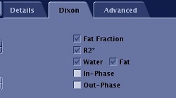
- Select the Dixon images you want reconstructed (in-phase or out-of-phase).
- Fat, Water and R2* are automatically selected for IDEAL IQ and therefore they cannot be de-selected.
- To view IDEAL IQ images, from the Patient List, select the desired IDEAL IQ series.
- The IDEAL IQ scan generates images using the following convention.
Table 1. IDEAL IQ series. Note that all the patient list series text includes the scan plane, for example: R2*: Axial IDEAL IQ Series Description N, Input series = N Triglyceride fat fraction imagesSeries description in patient list: FatFrac: IDEAL IQ 100*N R2* mapsSeries description in patient list: R2*: IDEAL IQ 100*N + 1 Water imagesSeries description in patient list: Water: IDEAL IQ 100*N + 2 Triglyceride fat imagesSeries description in patient list: Fat: IDEAL IQ 100*N + 3 In PhaseSeries description in patient list: InPhase: IDEAL IQ 100*N + 4 Out of PhaseSeries description in patient list: OutPhase: IDEAL IQ
Figure 2. Example of IDEAL IQ images 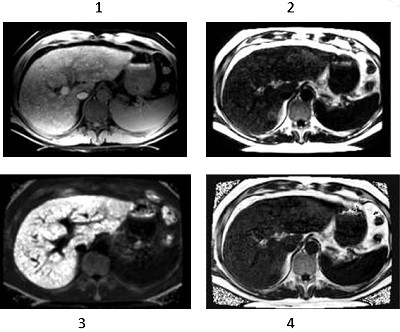
Table 2. Image legend Number Description 1 T2* corrected water IDEAL IQ image 2 T2* corrected triglyceride fat IDEAL IQ image 3 R2* map IDEAL IQ image 4 Triglyceride fat-fraction IDEAL IQ image - The IDEAL IQ scan generates images using the following convention.
Results
Considerations
| Warning | |
|---|---|
- Some IDEAL IQ prescriptions may reach system memory limits, resulting in a failure at download. Any of the following methods can be used to resolve this issue.
- Wait for queued reconstruction jobs to finish.
- Reduce the Slices per Slab value.
- Reduce the Phase value.
- IDEAL IQ image quality depends on the spacing of the IDEAL echoes where the optimal range of spacing is between 0.5p and 0.95p phase shift between triglyceride fat and water. A small echo spacing will result in noisy water-triglyceride fat separation, where as an echo spacing greater than the optimal range is vulnerable to water-triglyceride fat swap. Echo spacing is determined by scan parameters such as receive bandwidth and Frequency resolution (FOV and Frequency value). If your scan parameters force the echo spacing phase shift to be outside the optimum range, the PSD will post one of two messages:
- "Echo-spacing NN PI is above 0.48PI limit. Increase RBW."
- "Echo-spacing NN PI is below 0.96PI and 1.5PI. Change ETL/RBW/FOV."
- "Echo-spacing NN PI is above 1.5PI. Decrease ETL or Increase RBW."
where NN is the echo spacing phase shift of your prescription. Modify your scan prescription to keep the echo-spacing phase shift within 0.48PI to 0.96PI. If your echo spacing is smaller than 0.48PI, increase your frequency resolution or reduce the receiver bandwidth. If your echo spacing is greater than the range, reduce your frequency resolution or increase the receiver bandwidth. If your echo spacing is outside the advised range and error message is posted advising corrective action.
- There may be local areas of water-triglyceride fat swap when there is severe Bo field variation due to patient inhomogeneity, air cavity, metal implants, and the presence of iron deposition, etc. The presence of other imaging artifacts may also cause incomplete water-triglyceride fat separation, such as parallel imaging artifact, patient motion and aliasing in the phase encoding direction.
- When there is sufficient iron overload, T2* can be extremely short (<2ms). In these cases, the source echoes may not possess enough SNR for a good water-triglyceride fat separation. As a result, when R2* in liver is greater than 500 Hz (T2* < 2ms), water/triglyceride fat/triglyceride fat-fraction images may be noisy.
- Do not use fat fraction and/or R2* map value as a single source for any diagnosis.
- There may be residual phase error when phase correction fails in IDEAL-IQ. Please always check the fat fraction value from spleen and confirm the value is less or equal to 3%. If the value is greater than 3%, please redo the scan or reach GE representative to check the scanner.