

- 00000018WIA302C0970GYZ
- id_400249721.5
- Mar 24, 2022 5:09:37 PM
3DASL
Before you begin
3DASL is a non-invasive, one-click application that allows whole brain CBF measurements. It uses a 3D Spiral FSE pulse sequence with Extended Dynamic Range Imaging Option to acquire a set of images (PW and PD) which post-process into CBF image maps.
About this task
Use these steps to acquire contrast-free CBF 3D brain scans for a wide application of pathology such as stroke, tumor, neuro degeneration, etc.
Step-by-step instructions
- Position the patient so that the head is straight and does not tilt left or right.3DASL has a labeling pulse that is acquired at the level of the carotids. If the head is tilted left or right the labeling pulse is not acquired at the same left/right anatomical location and thus the CBF calculations are undesirable. The result is uneven contrast or shading between hemispheres.
Figure 1. 3DASL images with head straight and head tilted 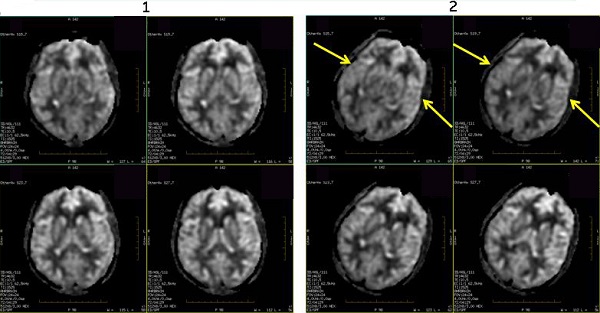
Table 1. Image legend Number Description 1 Head is positioned straight, nose up. Note the even contrast between right and left hemispheres. 2 Head is tilted towards the left. Note the uneven contrast between the right and left hemispheres. - For optimal image quality, prescribe an axial, single 3D slab that completely covers the brain. For optimal image quality and to minimize slab wrap artifact, the slice coverage should be from the bottom of the cerebellum to the top of the head.
Figure 2. Example of 3DASL slab locations 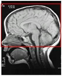
Results
Arterial blood flows to the brain. A spatially selective inversion continuous pulse is applied that, in effect, labels protons as they move into tissue. The inverted blood results in a decreased signal on a PD image.
3DASL uses a continuous labeling technique that results in the following:
- Higher SNR in comparison to pulsed RF labeling.
- Less T1 decay occurs since the protons are inverted closer to the imaging volume.
- Mag transfer effects are reduced, which increases labeling efficiency.
- Less motion sensitive than pulsed RF labeling.
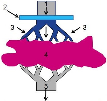
| Number | Description |
|---|---|
| 1 | Arterial blood flowing into brain |
| 2 | Spatially selective inversion pulse |
| 3 | Inverted spins |
| 4 | Brain tissue |
| 5 | Venous outflow |
Two sets of images are acquired: one with the spatially selective inversion pulse (inverted blood) and one without the spatially selective inversion pulse (non-inverted blood). These two data sets are subtracted, which removes signal from the static background and the result is images that are proportional to cerebral blood flow. Multiple data sets are acquired to make a CBF image.
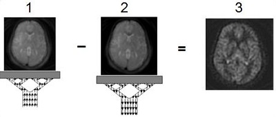
| Number | Description |
|---|---|
| 1 | Inverted blood, control image |
| 2 | Non-inverted blood, label image |
| 3 | CBF image |
- The ASL images are labeled as ASL type in the patient list.
Figure 5. ASL type in Patient list 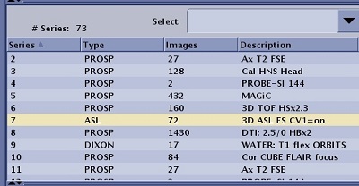
- Post-processed images are labeled as PROC and the description includes CBF.
Figure 6. Post-processed ASL images with description of CBF 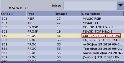
- If you prescribe a post process task, from the Workflow Manager, select the 3DASL CBF post process task and click Run.
- If you select Automatic from the Post Process screen, then the CBF and Reformat images are automatically generated.
- If you did not prescribe a post process task, you can view the CBF maps in READY View: ASL optional procedures.
- For details about 3DASL series numbering, see Series numbering.
Image annotation
For details, see Application annotation.
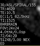

LT is the labeling time annotated in the upper left-side of a PW image.