- 00000018WIA303D4970GYZ
- id_400248941.3
- Aug 21, 2022 3:47:49 PM
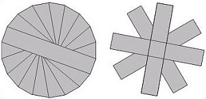
PROPELLER scan parameters selections
Consider this information when modifying the scan parameters for all types of PROPELLER scans. For specific scan parameter values, select a protocol from your GE or Site library.
Typically use PROPELLER to acquire brain, spine, liver, pelvis, shoulder, knee and wrist images.
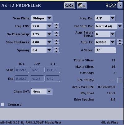
Scan Parameters
Consider the following information when selecting PROPELLER scan parameters. Note that not all options are available with every PROPELLER PSD. If the option or scan parameter is not available, it does not appear on the screen.
Imaging Options
- ARC considerations
- Acoustic Reduction Technology
- Fast Recovery
- IR Prepared
- Navigator: tab and screens
- Respiratory Gating/Triggering
- T1 FLAIR
- T2 FLAIR
- Tailored RF
| Parameter | Description |
|---|---|
| Scan Plane | For details, see Scan Plane |
| Anatomical Region | For details, see Anatomical Region for tasks. |
| Calibration in Prescan | For details, see Calibration scan procedure. |
| No Phase Wrap |
|
| Spacing | For details, see Slice Spacing. |
| Start/End | Defines the start and end locations in three planes: Superior/Inferior, Right/Left, Anterior/Posterior. |
| Chem Sat (Chemical Saturation) |
|
| Freq Dir (Frequency Direction) | For details, see Frequency Direction. |
| Fat Shift Dir (Fat Shift Direction) | It used to define the display direction from fat signal. For details, see Fat shift direction. |
| Acqs Before Pause (Acquisitions Before Pause) | For details, see Pause before scan. |
| TR and Auto TR |
|
| # Slices | The number of slices in a scan prescription. |
| # of TEs per Scan | It is the number of TE that can be acquired per acquisition. It is frequently referred to as number of echoes. |
| TE |
|
| TI and Auto Inv. Time (Auto Inversion Time) |
|
| Refocus Flip Angle | Adjusting the Refocus Angle is typically applied to any musculoskeletal scans. Reducing the flip angle results in increased signal from cartilage. Adjust the refocus angle based on the desired image contrast. As the value decreases, the fluid signal becomes darker. Consider these refocus angles:
|
| Echo Train Length | As the ETL increases:
|
| Intensity Correction | For details, see Intensity Filter and Intensity Correction. |
| Save Original | For details, see Save Original. |
| 3D Geometry Correction | For details see, 3D Geometry Correction. |
| Harmonize |
|
| Frequency | For details see Phase and frequency. |
| NEX |
|
| Bandwidth |
|
| Excitation Mode | For details see Excitation Mode. |
| Shim | Select the Shim value to Auto or On. For details, see: Shim volume |
| RF Drive Mode | For details, see RF Drive Mode. |
| Phase Correct | For details, see Phase Correct. |