

- 00000018WIA3005A870GYZ
- id_400217171.10
- Aug 19, 2022 5:19:38 PM
FSE scan
An FSE pulse sequence allows multiple 180° refocusing pulses that fill multiple lines of k-space in one TR period. The lines of k-space filled within a TR period is determined by the ETL. The Echospace is the time between each echo. ESP is clinically useful to get an idea of how much blurring is expected for a given ETL. For more ESP details, see Echo Train Length (ETL).
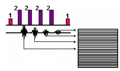
| Number | Description |
|---|---|
| 1 | 90° |
| 2 | 180° |
Use FSE to acquire T1-, PD-, and T2-weighted image contrast.
Consider this information when modifying FSE scan parameters. For specific scan parameter values, select a protocol from your GE or Site library.
- Scan selections for 2D: 2D Mode, Fast Spin Echo family, FSE pulse.
- Scan selections for 3D: 3D Mode, Fast Spin Echo family, FSE pulse.
General considerations
- FSE uses an increase of RF power to obtain the proper flip angles (calculated during prescan) in comparison to FSE. This is reflected in increased TG gain values during prescan.
Scan parameters
- Excitation Mode: If 3D mode is selected, from the scan parameters Details screen, consider selecting Excitation Mode: Focus to reduce phase alias artifact when a small FOV is used.
-
Note: Focus is sensitive to B0 inhomogeneities and thus placement of a local shim box around the region of interest is highly recommended to achieve better image quality.
- When Focus is selected, the Phase FOV (on the scan parameter screen) can have a factor from 0.2 to 0.9.
-
- FOV: If the FOV is ≤ 16 and the slice thickness is ≤ 5, then the ESP may increase and there may be fewer slices per acquisition.
- Phase: A phase value of 512 significantly reduces edge blurring.
- NEX: If an odd NEX is selected, it may (although unlikely), result in reduced spatial resolution in comparison to the same scan parameters with an even NEX.
- Slice/Slabs: If 3D mode is selected, then select Slices per Slab and # of Slabs. When six Slices per Slab with Slices to Discard set to 1 are prescribed with a 3D FSE scan, some slice locations are duplicated. For example, slice one = location L26.5, slice two = location L25.5, slice three = location L24.5, slice four = location L23.5, slice five = location L24.5, slice six = location L23.5. Therefore, select eight locs per slab for 3D FSE prescriptions.
- TE: Fractional echo (Minimum) is not allowed with FSE.
- TE: If the selected TE is less than the ESP, the effective TE increases to the ESP value.
- TE: Consider selecting an effective TE that is close to the midpoint of the TE Min/Max range to minimize FSE blurring.
- Consider selecting Real Time Center Frequency for FAT SAT. For details, see Real Time Center Frequency
Imaging Options
- Flex: It enables a water-fat separation technique that can used in place of conventional fat saturation to produce water-only images.
- Flow Compensation: If Flow Compensation is selected from th Imaging Options screen, then select the Flow Comp direction in the direction of the moving protons. Flow Compensation with FSE only corrects flow in one direction. If Phase and Frequency have been swapped, do not use Flow Compensation.
User CVs
Click the Advance tab to view the available User CVs. The CVs may vary based on the field strength and selected scan and imaging parameters.
- Acquisition order
- Apodization Level
- Black-Blood Slice Factor
- Blurring Cancellation
- Dynamic TG
- Enhanced fine line suppression
- Extreme High Resolution Optimization
- Fast Single TR Bipolar Acquisition is available when Flex Imaging Option is selected.
- Fat Saturation efficiency
- FSE T1 Optimization
- Half NEX Enhancement when NEX value = 0.5
- Motion Sensitivity Reduction
- SAR Optimization
- Spatial SAT Type
- TR Range for Auto TR, for details see Auto TR.