

- 00000018WIA30093970GYZ
- id_400246261.4
- Aug 19, 2022 4:45:19 PM
SSFSE and SSFSE-IR
SSFSE and SSFSE-IR use an RF pulse design that allows for significantly short ESP and a 0.5 NEX technique that acquires a data set within a single RF excitation period.
In SSFSE, the minimum TE does not equate to the ESP.
The scan time for an SSFSE acquisition = (Acquisition Rate + SAR Delay) x (# of Slices). The Acquisition Rate is the product of the ETL times the ESP.
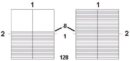
| Number | Description |
|---|---|
| 1 | Frequency |
| 2 | Phase |
Use SSFSE for:
- to reduce motion artifact and imaging time.
- to scan uncooperative patients in short scan times.
- for breath hold abdominal and cardiac imaging.
- with long TE values (300-1300 ms) to image the gallbladder and biliary tree.
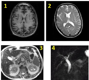
| Number | Description |
|---|---|
| 1 | T1 bain |
| 2 | T2 brain |
| 3 | Abdomen |
| 4 | Gallbladder |
Consider this information when modifying SSFSE and SSFSE-IR scan parameters. For specific scan parameter values, select a protocol from your GE or Site library.
- Scan selections: 2D Mode, Fast Spin Echo family, SSFSE pulse.
- SSFSE-IR scan selections: 2D Mode, Fast Spin Echo family, SSFSE pulse, IR-Prepared Imaging Option.
General considerations
- When performing an SSFSE sequence, if the patient weight is 75 Kg (170 pounds) or higher, it is probable that Auto Prescan will fail and the following message will be posted, "Maximum power reached, check patient weight entered". If this occurs, click Manual Prescan and check the TG. Set the maximum value to 200. Exit Manual Prescan, then click Scan.
- SSFSE can be acquired with bilateral shims. Typically use with fast T2-weighted bilateral breast images to reduce off-resonance effects.
Abdomen and pelvis considerations
- Tailored RF Imaging Option and No Phase wrap are available with SSFSE and SSFSE localizer for improved image quality in the abdomen and pelvis. Some GE SSFSE abdomen and pelvis protocols have been updated with these SSFSE enhancements.
- Tailored RF for SSFSE applies a train of refocusing RF pulses with modulated flip angles. They are designed to extend the signal from tissue throughout the echo train and reduce the equivalent TE. The flip angles are automatically calculated based on the echo train length and view ordering.
Scan parameters
- Bandwidth: To lessen the edge blurring that occurs with SSFSE or SSFSE-IR (except for maximum TE applications), increase the RBw and decrease the PFOV at the expense of decreasing SNR.
- Frequency/ FOV/ Bandwidth: As the ESP gets longer, the signals are collected over a greater part of the T2 decay curve. Shorten the ESP and more echoes can be acquired over a comparatively shorter portion of the T2 decay curve. To decrease ESP, decrease the frequency matrix value, increase FOV, or increase the bandwidth.
- NEX:
- The fractional NEX method in SSFSE and SSFSE-IR contributes to edge blurring.
- Multiple NEX can be selected from the NEX menu.
- No Phase Wrap:
- When No Phase Wrap factor is set to a value greater than 1.0, it allows the patient to have arms at the side, which may increase patient comfort.
- A larger NPW value increases the ETL, which may increase image blurring. To preserve image sharpness decrease the Phase value.
- A slight increase in SNR due to more noise averaging that occurs with NPW.
- TE: The TE selection determines the k-space filling technique.
- Linear Phase Encoding is used for short to medium range TEs.
Figure 3. Linear View Ordering 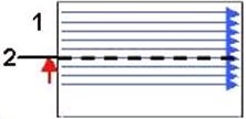
Table 3. Image legend Number 1 Ky 2 TE1
- Linear Phase Encoding is used for short to medium range TEs.
- Reverse Phase Encoding is used for long range TEs and minimizes SNR loss since it acquires more echoes earlier in the echo train compared to Linear Phase Encoding.
Figure 4. Reverse Linear View Ordering: 1 = Ky, 2 = TE2 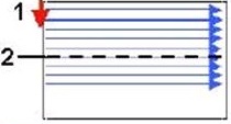
Table 4. Image legend Number 1 Ky 2 TE2 - When selecting the maximum TE value, consider using high matrix values, PFOV = 1, and the smallest allowable RBw.
- For a T2 SSFSE, select a TE value between the Min and Max range of TE values listed at the bottom of the Details screen.
- For an MRCP or myelogram image, select a TE value within the range of TE2 values listed next to the TE2 type-in field.
- TR: Select a TR between Minimum and 16,000 ms. When selecting Minimum, select 1 loc before pause to avoid cross-talk. Alternatively, use a long TR such as 4000 ms, which results in an approximated acquisition time of 1 second and a pause time of 3 sec.
Imaging Options
- Fast Recovery Imaging Option for long T2-weighted images that use a short TR. For details, see Fast Recovery.
- Multi-phase Imaging Option can be selected with multiple slices and not require the selection of cardiac or respiratory gating or triggering Imaging Options.
- Sequential: Select it to eliminate the image shift often observed with interleaved breath-hold abdominal scans, when those images are acquired for MIP post processing.
- Sequential acquires the slices in numerical order. If you do not select sequential, an interleaved acquisition is used, first acquiring the odd, and then the even slices.
- Sequential can result in a decrease in SNR and contrast in comparison to an interleaved acquisition.
Multi-slice or Snapshot SSFSE
- The efficiency of Navigated and Respiratory Triggered scans is improved by collecting multiple slice locations per trigger event. When Navigated and Respiratory Triggering imaging option is selected, 1-3 slice locations per trigger are acquired. The number of slices per trigger is calculated automatically based upon series parameters and respiratory rate.
Figure 5. Abdomen comparison images 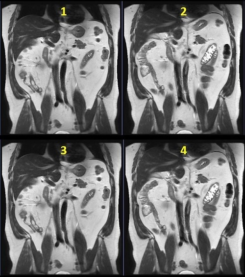
Table 5. Image legend Number Description 1 Breath Hold: 32 seconds 2 3 locations per trigger: 1:12 3 2 locations per trigger: 1:48 4 1 location per trigger: 3:35 - For multi-slice SSFSE with Navigator Imaging Option scans, click the Run RR Measurement option button. This ensures that the respiratory rate can be calculated at download, and the number of locations per trigger updated accordingly.
Figure 6. Navigator tab 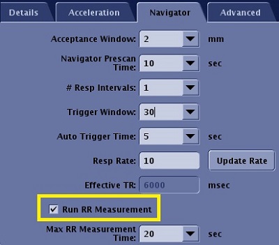
- For multi-phase and NEX > 1, the number of slice locations per respiratory/navigator trigger is limited to 1.
Tailored RF
- Tailored RF image quality improves when Minimum Full TE is used in areas with less motion.
- For Liver anatomy, the minimum flip angle is 90 degrees.
- When it is selected it may decrease the minimum TR value, which may be useful for acquiring a breath-hold scan with a larger coverage or a shorter scan time. It can also be used with a 3-Plane localizer.
- Tailored RF reduces the SAR.
- In areas of cardiac motion, Tailored RF may result in increased shading.
- Tailored RF may result in dark blood or fluid signal because of fast motion.
- Tailored RF is not compatible with the Imaging Option Blood Suppression.
- A TE longer than the Minimum Full TE may result in increased sensitivity to motion shading.
- Tailored RF is not recommended for MRCP scans.
- When acquiring images near the heart, it is recommended to use a gated technique if scanning with Minimum Full TE and Tailored RF. Typically, use peripheral gating and acquire the images at the diastolic phase.
- The effect of combining both Tailored RF and Minimum Full TE and User CV 1 is equivalent to fully sampling K-space which is equivalent to a 1 NEX scan.
User CVs
Click the Advance tab to view the available User CVs. The CVs may vary based on the field strength and selected scan and imaging parameters.