Frequency Direction is the scanning direction associated with the frequency encoding gradient. The phase and frequency axis determine the vertical and horizontal axis of the displayed image. The direction displayed is the default direction that is typically the long axis of the anatomy.
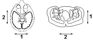
Figure 1. Default axial plane frequency directions
Table 1. Image legend
Number
Description
1
Phase
2
Frequency
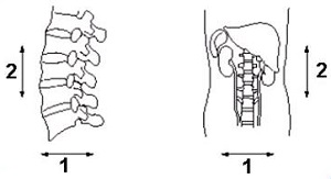
Figure 2. Default sagittal and coronal frequency directions
Table 2. Image legend
Number
Description
1
Phase
2
Frequency
Select a Frequency Direction to minimize flow artifact. Select the other direction to swap phase and frequency.
Table 3. Phase and Frequency directions
Coil
Plane
Frequency
Phase
Slice
Body, extremity, Neuro vascular, receive only surface coils
Axial
R/L
A/P
S/I
Sagittal
S/I
A/P
R/L
Coronal
S/I
R/L
A/P
Head coils
Axial
A/P with EPI R/L
R/L with EPI A/P
S/I
Sagittal
S/I
A/P
R/L
Coronal
S/I with EPI R/L
R/L with EPI S/I
A/P
Changes to the coil configuration files may change the default directions.
For oblique prescriptions, the frequency direction selections in the Freq DIR text box are Unswap or Swap. Unswap is the frequency direction displayed prior to prescribing oblique slices.
Flow, motion, and other phase artifacts, such as aliasing or wraparound, are mapped onto the image in the phase direction. A wise choice of frequency direction can reroute these artifacts away from the region of interest. For example, sagittal spines have the frequency direction in the S/I direction and phase A/P, which routes motion artifacts through the vertebral bodies and spinal canal. One solution is to make phase run S/I so that the flow artifact from the aorta and vena cava runs parallel to the cord, rather than through it.