

- 00000018WIA30D64870GYZ
- id_400230671.5
- Apr 27, 2022 4:31:25 AM
Advisory area
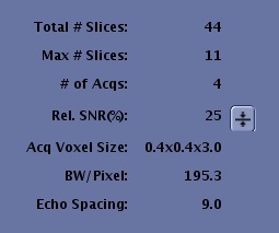
Review the content in the Advisory area on the Scan Parameter screen before you start a scan. There are a maximum of 10 parameters that can be displayed. The Advisory area content changes based on the PSD of the active series. If the Advisory parameter does not display it is because it is not compatible with the PSD. Make adjustments as needed based on Scan parameter trade-offs. As scan parameters are adjusted, the display updates.
| Item | Description |
|---|---|
| Total # Slices | The total number of slices prescribed. |
| Max # slices | The maximum slices allowed for a single acquisition based on the selected series. |
| # of Acqs | The number of acquisitions for the current series. If the number of slices prescribed exceeds the value displayed in Max # of Slices, then an acquisition is added to the series. |
| Rel SNR(%) | The Relative SNR% meter reflects changes to parameters within a prescription that impact Signal-to-Noise Ratio (SNR). The parameters used to calculate changes in SNR are:
The relative SNR% is not an absolute value but a relative value based on the current set of parameters being equal to 100%. Changes made to parameters that affect SNR are calculated and relative SNR% is updated to indicate their affect on SNR. The relative SNR% for a protocol can be reset to 100% by clicking the Reset SNR arrow. Changes for SNR are not calculated for changes in TR or TE. Significant changes in TR and TE can change the SNR for an acquisition. The calculation does not include changes for TR, PSD, or coil selected. For a variable SE sequence, a relative SNR% is given for TE and TE2. |
| Acq Voxel Size |
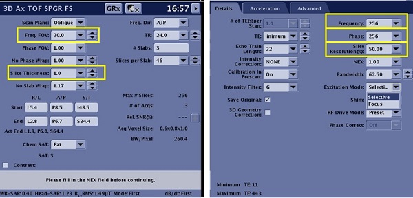
Acquired voxel size is calculated from the Frequency FOV the slice thickness together with the Frequency, Phase, and Slice Resolution (3D only). It relates to sharpness and SNR in the image; the smaller the voxel size the sharper the image and the lower the SNR. The Acquisition Voxel Size is annotated as vX x vY x vZ where:
 |
| BW/Pixel | Bandwidth/Pixel is the readout bandwidth divided by the series X-resolution expressed in Hz. It is clinically useful to relate what fraction of a pixel size fat will be shifted relative to water when they are present together in a single tissue. BW/Pixel is only displayed for multi-echo prescriptions where the readout bandwidth is the same across the echoes. |
| Echo spacing | Echo space is displayed for Fast Spin Echo (FSE) and Echo Planar Imaging (EPI) series. It is clinically useful to get an idea of how much blurring is expected for a given Echo Train Length (ETL). |
| Effective resolution (not shown) | It is only displayed for Spiral-based acquisition and DWI PROPELLER. It is displayed in millimeters and based on the acquired resolution and the reconstruction resolution. |
| Temporal resolution | It displays the Frames per Second (FPS) notification is displayed during Real Time Imaging acquisitions. FPS is dependent on the system hardware configuration. The FPS rate for the prescribed series appears prior to the beginning of the scan. |
| Recon Time | Reconstruction time appears for IDEAL acquisitions. It indicates an estimate of the reconstruction time for all IDEAL images. |