

- 00000018WIA3066A870GYZ
- id_400256831.4
- Aug 19, 2022 5:01:12 PM
FLAIR scan
The FLAIR pulse sequence is a Fast Inversion Recovery technique. Like FSE-IR, it consists of an initial 180° inversion pulse prior to the 90° excitation pulse.
With a T2 FLAIR, the TI is based on the null point of CSF.
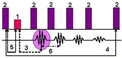
| Number | Description |
|---|---|
| 1 | 90° |
| 2 | 180° |
| 3 | TE |
| 4 | TR |
| 5 | TI |
| 6 | Echo Space |
Use T1 FLAIR to acquire head and spine T1-weighted image contrast.
| Number | Description |
|---|---|
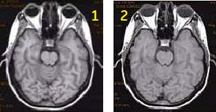
| 1 | T1 FLAIR brain |
| 2 | Spin Echo brain |
Use T2 FLAIR to acquired images to suppress bright CSF signal that is adjacent to fluid filled structures.
Consider this information when modifying T1 FLAIR and T2 FLAIR scan parameters. For specific scan parameter values, select a protocol from your GE or Site library.
T1 FLAIR parameter selections
- Scan selections: 2D Mode, Fast Spin Echo family, FSE pulse, T1 FLAIR Imaging Option.
- Auto TI: It is available to automatically calculate the optimum TI value as the TR, slice thickness and spacing vary. Use Auto TI for consistent CSF suppression.
- Auto TR: Automatically selects the optimum TR and TI for CSF suppression, optimum gray/white matter contrast, and shortest scan time. Note that when Auto TR is selected, Auto TI locked On.
- FOV: If the FOV is ≤ 16 and the Slice Thickness is ≤ 5, the ESP may increase and there may be fewer slices per acquisition.
- NEX: If an odd NEX is selected, it may (although unlikely), result in reduced spatial resolution in comparison to the same scan parameters with an even NEX.
- Pause: Pausing a FLAIR acquisition during scanning may cause image artifacts and should be avoided.
- Slice/Slab: There is a variation in the signal intensity of a T1 FLAIR acquisition when the slice spacing is less than the slice's thickness. This may result in a decrease in signal on the first and last slice, or every other slice may vary in signal intensity. To avoid this problem set the slice spacing to equal the slice thickness or use the Interleave option on the slice spacing menu. Using Interleave doubles the scan time.
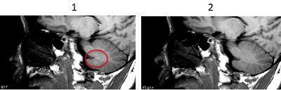
- TI: When performing a T1 FLAIR with contrast, if the T1 shortening of contrast corresponds to the null point of the enhancing lesion, contrast enhancement could be suppressed. Note the differences in lesion enhancement on the sagittal T1 cervical spine images shown below.
Figure 4. Spine image comparison: T1 FLAIR (left) and Spin Echo (right) 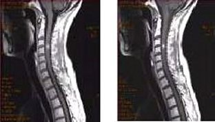
Sagittal T1 FLAIR ASSET artifact
An aliasing ASSET artifact can occur on sagittal T1 FLAIR scans when phase encoding is in the typical Anterior/Posterior direction. In general, turn off ASSET when acquiring sagittal T1 FLAIR scans; the non-ASSET acquisition time penalty is minimal and the SNR is improved.
| Number | Description |
|---|---|
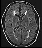
| 1 | ASSET Imaging Option turned on. |
| 2 | ASSET Imaging Option turned off. |
T2 FLAIR parameter selections
- Scan selections: 2D Mode, Fast Spin Echo family, FSE pulse, T2 FLAIR and Tailored RF Imaging Options.
- Auto TI: It is available to automatically calculate the optimum TI value as the TR, slice thickness and spacing vary. Use Auto TI for consistent CSF suppression.
- ETL: Based on your selection of TE, FOV, x-resolution, and bandwidth (which determines the ESP), the FLAIR pulse sequence chooses the appropriate ETL. Therefore, ETL is not a selectable parameter.
- Since ETL is tied to the TE, as you select shorter TEs, the scan time increases.
- FOV: If the FOV is ≤ 16 and the slice thickness is ≤ 5, the ESP may increase and there may be fewer slices per acquisition.
- NEX: If an odd NEX is selected, it may (although unlikely), result in reduced spatial resolution in comparison to the same scan parameters with an even NEX.
- TR: To maintain CSF nulling, the TR must be at least 3 to 4 times the value of the TI. If you choose a TR that is significantly lower than 3 times the TI, the quality of the CSF nulling is degraded.
User CVs for T1 and T2 FLAIR
Click the Advance tab to view the available User CVs. The CVs may vary based on the field strength and selected scan and imaging parameters.
- Acquisition Order
- It is for enhflair type-in.
- Blurring Cancellation
- Dynamic TG
- Edge Slice CSF Suppression
- It can be used to suppress the CSF signal at the edge slices.
- Enhanced fine line suppression
- Extreme High Resolution Optimization
- Fat Saturation Efficiency
- Half NEX enhancement
- Minimum Acquisition
- It is only for T2 FLAIR.
- The CV only appears if ARC is disabled and Optimized mode is turned off by setting opuser5 to 0.
- Motion Sensitivity Reduction
- It is only for T2 FLAIR and turns on T2 FLAIR optimization.
- Spatial SAT Type
- SAR Optimization
- TR Range for Auto TR, for details see Auto TR.
The Optimized T2 FLAIR Sequence User CV turned on (1 = 0n), generates images with higher contrast-to-noise ratio (CNR) of gray/white matter while keeping cerebral spinal fluid (CSF) suppressed.
The GE recommended protocols have been significantly changed to take advantage of T2 FLAIR optimized. Consider the following when the CV is turned on:
- Optimized scan parameters provide more slices per acquisition time.
- A CSF inversion algorithm that suppresses CSF when a longer TI value is used. This helps to obtain high gray/white matter CNR.
- Allows partial Phase FOV for optimized scan time.
- Allows a new scan parameter Refocus flip angle to achieve optimal gray/white matter contrast. A flip angle of 160 is recommended.
- Select Inversion Time scan parameter Auto to produce optimum gray/white matter contrast. Once Auto is selected, the scan parameter changes to Auto Inversion Time.
- Enables ARC Imaging Option, which allows scan time optimization for a given slice coverage.
- Enables Fat Saturation to:
- Suppress skull fat, which helps reduce ringing/ghosting artifacts from the skull.
- Improves visualization of gray/white matter at outer edges of the brain.
- Provides fat suppression within brain anatomy.
- Allows editable ETL for a given TE to produce optimal gray/white matter contrast.
- Typically select an Acceleration factor of 2 and select Fat as the Chem SAT option.
Figure 6. Mid-brain FLAIR comparison 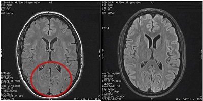
Post-process tasks
There are multiple compatible post-process tasks. For details, see Add post-process task.
- Maximum Intensity Projection
- Multi Planar Reconstruction
- Image Enhancement Filters
- Pasting