

- 00000018WIA3003F770GYZ
- id_400259421.3
- Mar 29, 2022 2:43:54 PM
Active annotation
About this task
Step-by-step instructions
- The following procedures describe how to manipulate each of the active annotation fields. It assumes that Full annotation is selected as the preference.
Figure 1. Volume Viewer active annotation screen 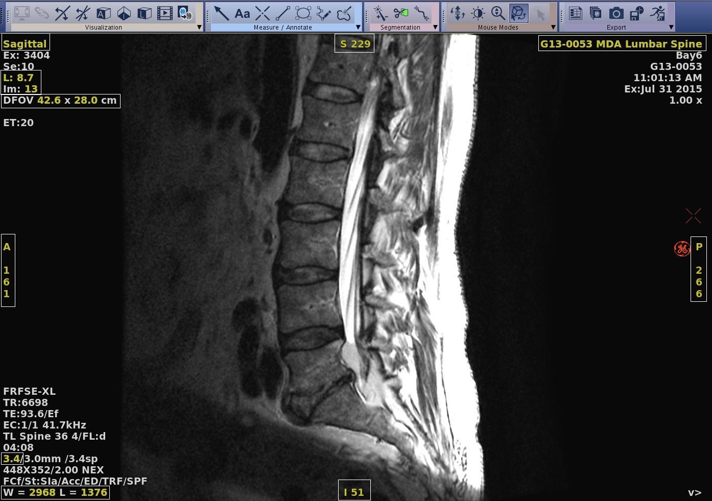
Table 1. Active annotation procedures Active annotation Procedure View type 
Left or right-click and select a view type from the menu.Figure 2. View Type menu that may vary based on the image in the viewport 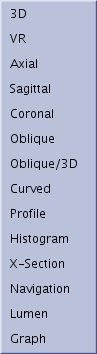
- The type of view displayed in each of the four views of the viewing area is determined by the selected protocol.
- During image processing, you can change the view at any time using the active annotations. The term "coi" on an oblique view refers to the center of the image.
Parametric or Functional Annotation Figure 3. Top line: Plane annotation followed by series type/parametric map annotation 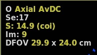
Click the parametric map (time course, diffusion, functional, or metabolite) annotation and make a selection from the menu.
- For more details, see Change the image/map in a viewport.
Phase/Rank: typically use this with a time-course or fMRI data set. Method 1
Figure 4. Yellow phase/rank annotation in upper left corner of viewport 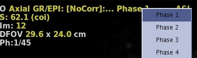 Click the yellow annotation from the top of the viewport and select a rank/phase from the Volume Selector menu.
- Alternatively, modify the rank annotation, at the middle bottom right area of the viewport.
Figure 5. Yellow phase/rank annotation in middle bottom right area of the viewport 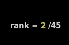
Phase/Rank: typically use this with a time-course or fMRI data set. Method 2
Figure 6. White vertical line (1) can be moved to desired phase/rank/time 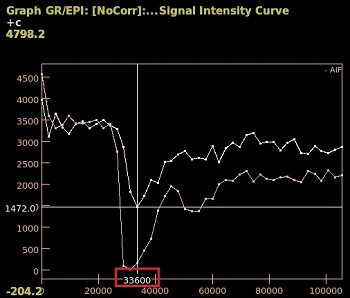 Click and drag the vertical white bar on the graph view to the desired rank/phase number.
- The yellow rank/phase/time annotation updates.
Scan location and slice number 
Middle-click and drag horizontally to scroll through the images or click to increment and right-click to decrement an image at a time.- Alternatively, you can use the left and right arrow keys on the keyboard to move through the image set. Scan location is not available on 3D views.
Slice thickness  Middle-click and drag horizontally to real-time change the slice thickness or click to increment and right-click to decrement the slice thickness on reformatted images.
- Slice Thickness is not a selection on a 3D or MPR 3D view.
MIP 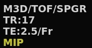
Click to change the MIP to another projection type.
Figure 7. MIP projection types 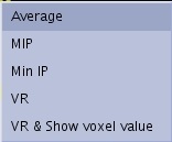
DFOV  Middle-click and drag horizontally to real-time magnify the image or click to increment and right-click to decrement the mag factor.
- The maximum zoom factor (ratio between acquisition DFOV and actual DFOV) is 8.0.
- You cannot increase the DFOV beyond the original value, unless the height of the stack of images (number of images × slice thickness) is larger than the DFOV. In that case, you can zoom up to the height of the stack of images (zoom factor < 1.0).
Window width and level 
Middle-click and drag vertically and horizontally to real-time change the W/L.
- Alternately, move the mouse over the annotation and type in a new value or right-click to display the W/L Preset menu.
To modify the window W/L of the reference images, click and hold the middle mouse button on the reference image and move the mouse as above.
Patient name 
Click or right-click and select Show or Hide to hide or show patient name.
Image roam 
After zooming in (decreasing the FOV), click and drag to move the image within the viewport.
Graph annotation CAUTION For details, see Active graph annotation.
Algorithm mode and cut plane This is 3D specific annotation.

Left or right-click the algorithm mode to select an option.
Left or right-click No Cut to display the list of cut planes.
Figure 8. This menu may be slightly different depending on the image type and rendering mode selected in the viewport. 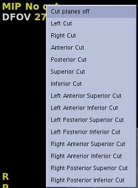
No VOI This is 3D specific annotation.
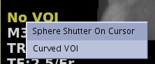 Left or right-click No VOI and select Sphere Shutter on Cursor or Curved VOI.
- For details, see Draw a shutter around anatomy of interest.