

- 00000018WIA30914970GYZ
- id_400261751.4
- Aug 21, 2022 2:56:31 PM
SWAN scan
Use SWAN to acquire 3D, high-resolution, susceptibility enhanced (heavy T2*-weighted) multi -echo gradient echo head scans that produce echo-combined images. It reduces geometric distortion and the high bandwidth (31.25 kHz or higher) helps to avoid chemical shift artifacts. Both paramagnetic and diamagnetic tissues show similar behavior on magnitude images generated from the SWAN application. SWAN phase images provide enhanced visualization of local magnetic field changes in the presence of paramagnetic and diamagnetic substances.
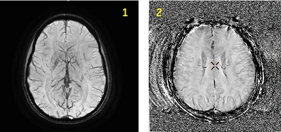
| Number | Description |
|---|---|
| 1 | SWAN reformatted image |
| 2 | SWAN Phase reformatted image |
Consider this information when modifying SWAN scan parameters. For specific scan parameter values, select a protocol from your GE or Site library.
- Scan selections: 3D Mode, Gradient Echo family, SWAN pulse.
Scan parameters
- Phase: From the Phase image menu, make a selection for the phase image's pixel values and their interpretation.
Figure 2. Phase Images menu for SWAN acquisitions 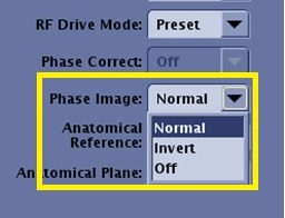
- Normal applies a convention where the dark areas on an image are considered hypo-intense and the brighter areas are considered hyper-intense.
- Invert applies a convention that inverts the pixel values compared to Normal.
- Off results in no phase images generated.
- Phase Image considerations:
- The phase images may not optimally unwrap in areas of inhomogeneity such as implants and air/tissue interfaces (for example sinuses).
Figure 3. SWAN reformatted and phase images 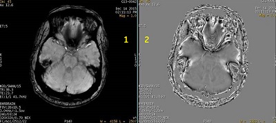
-
Table 2. Image legend Number Description 1 SWAN reformatted image that shows area of low signal due to inhomogeneity of anatomy. 2 Reformatted phase image shows non-optimal phase un-wrapping at the inhomogeneous region of anatomy. - When Phase images are generated, a prospective Phase series (described as FILT_PHA) appears in the patient list. For details, Series numbering. Reformatted images can be generated from this series.
- Viewers that are not DICOM compliant may result in pixels with negative values not displaying on the phase images.
- Your current MR system restricts the application of image enhancement filters on phase images. However, on legacy systems, image enhancement filters can be applied on phase images. Recommendation: do not apply image enhancement filters on legacy system images, and if you do, don't use those images for diagnostic purposes.
- The phase images may not optimally unwrap in areas of inhomogeneity such as implants and air/tissue interfaces (for example sinuses).
Imaging Options
- ASSET: It allows faster scanning when using ASSET compatible coils.
- Flow Comp: Use it with sagittal and coronal acquisitions when flow is parallel with the readout direction.
Image annotation
- When Invert is selected from the Phase Image menu on the Details tab, the phase images have the annotation “INV” in the bottom left corner of the image.
Figure 4. INV annotated in lower left corner of image viewport 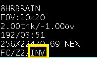
- The PHA annotation may not display on other MR or AW legacy systems.
Figure 5. Upper left corner image annotation on a phase image in the Viewer 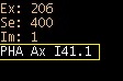
Figure 6. Phase image annotation in the Volume Viewer 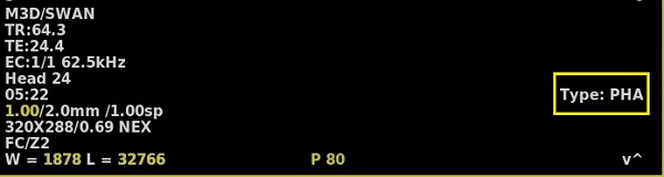
- Graphically deposit and position a single slab.
User CVs
Click the Advance tab to view the available User CVs. The CVs may vary based on the field strength and selected scan and imaging parameters.
Post-process tasks
There are multiple compatible post-process tasks. For details, see Add post-process task.
- Maximum Intensity Projection
- Multi Planar Reconstruction
- Image Enhancement Filters