Auto Contour: contour semi-spherical structures on 3D images
Before you begin
Consider this information before you begin using Auto Contour:
The precision of the auto contour is dependent on the slice thickness of the series. A thin slice 3D volume creates optimum results. Always scroll through the slices to ensure the expected contour.
About this task
Use these steps to contour semi-spherical structures on 3D MR images (hyper-signal or hypo-signal) and on PET images to obtain the SUV threshold units. Auto Contour information can then be displayed and structures can be compared side-by-side for follow-up.
Step-by-step instructions
Open the MR General Review.
From the Measure/Annotate Toolbar, click the Auto Contour icon ( ).
Result
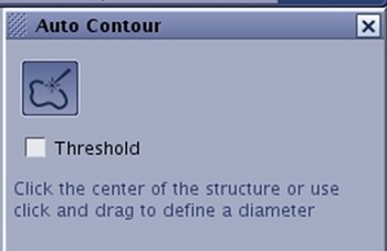
The Auto Contour screen appears. Figure 1. Auto Contour screen
Use one of the following steps to deposit an Auto Contour.
From the Auto Contour screen, click the Threshold option box and place the cursor in the center of the area of interest and left-click.
This option is often used for functional images to calculate minimum, maximum, average, volume etc., values.
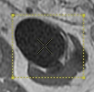
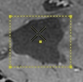
A boundary box with a contour based on the maximum value contained within the box displays. To change the contour size, click and drag a end point handle in each corner. Figure 2. Threshold option selected
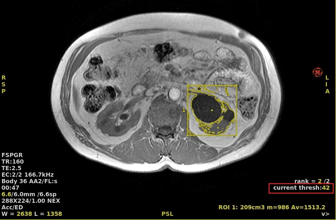
In the lower right corner, place the cursor over the active current threshold text and right-click to increase and left-click to decrease the threshold. Figure 3. Active threshold text
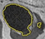
Do not click the Threshold option box and click in the center of the structure.
Figure 4. Auto Contour deposited in center of area of interest
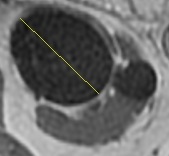
Do not click the Threshold option box and define a diameter on the structure (drag and drop) on any plane (axial, coronal, sagittal, oblique).
Figure 5. Diameter defined within area of interest
From the Auto Contour screen, click and drag the slider to adjust the contour size.
Scroll through the slices to ensure the contour of the area of interest is encompassed on all slices. Make adjustments as needed using the slider bar.
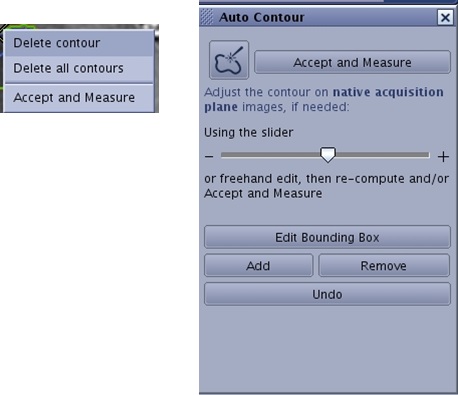
From the Auto Contour screen or from the right-click menu, click Accept and Measure.
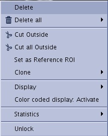
Figure 6. Right-click menu and Auto Contour menu
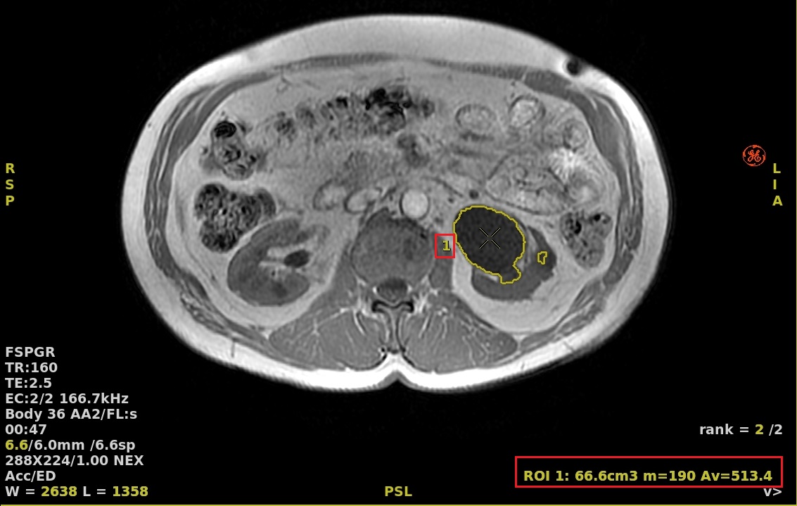
The contour is validated and structure information is displayed on the viewports. Figure 7. Auto Contour
To modify the structure information, complete the following:
Left-click the contour to make it active.
Right-click in the contour to view the menu and click the Statistics arrow.
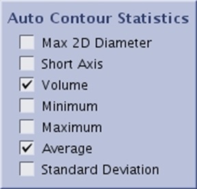
Click each desired option box. The structure information updates on the viewports.
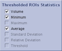
Figure 8. Example of Auto Contour Statistics screenFigure 9. Example of Threshold ROI Statistics screen
Optional: From the viewport that contains the contour, right-click in the image and not in the contour and select Transparent Background to display the auto contour structure on a transparent volume rendering of the whole volume.
Transparent background only works on Auto Contour created with these two methods:
Click in the center of the structure or,
Define a diameter on the structure (drag and drop) on any plane (axial, coronal, sagittal, oblique).
Note: Other Segment features such as Cut Outside can be applied to the auto contour structure.
To edit a contour, follow these steps.
If you have already clicked Accept and Measure you must first Unlock the contour. Click to make the contour active, right-click in the contour to view the menu and click Unlock.
Figure 10. Right-click menu
From the Auto Contour screen, click the Auto Contour icon () again. Respond to any prompts, as needed.
Option 1: From the Auto Contour screen, click and drag the slider to expand and contract the borders of the defined contour.
Option 2: place the cursor inside the contour and click and drag the middle mouse to adjust the slider.
Option 3: click the contour and the cursor becomes a pen. Click and drag the pen to trace the contour boundary on one or multiple slices (only on acquisition plane images) until the entire structure of interest is contoured.
Option 4:
From the Auto Contour screen, click Edit Bounding Box.
To move the center of the contour, click and drag the dot in the center of the box.
To change the contour size, click and drag any of corners of the box. Note you can change the box size from any view. You can also scroll through the images in any viewport to confirm that the contour is enclosing the structure of interest through out the volume.
Click Accept Box when all box size and location changes are finished. Figure 11. Bounding Box
If you have changed the contour's size or shape, click Re-compute to review the statistics and determine if more modifications are needed before you Accept and Measure.
Click Accept and Measure for each of the edit options.
To delete a contour while the Auto Contour is active, follow these steps.
Click the contour to make it active.
Right-click and select one of the following:
Delete contour
Delete all contours
To delete a contour that is not active (after you have clicked Accept and Measure), select Delete or Delete All from the right-click menu.


 ).
).