

- 00000018WIA30F02970GYZ
- id_400243701.2
- Aug 21, 2022 5:57:07 PM
TOF: 2D FGRE/FSPGR scan
Like TOF, Fast TOF imaging is based on conventional Gradient Echo scanning with flow compensation. This imaging technique relies primarily on flow-related enhancements to distinguish moving from stationary spins in creating MRAs. The 2D Fast TOF sequence can be acquired with a FastGRE or a FastSPGRPSD.
Fast TOF uses fractional echo, fractional RF, and wider receive bandwidth to obtain shorter TR and TE than standard TOF. Fractional RF shortens the duration of the excitation pulse and the readout time, thus shortening the overall total time required to apply the sequence.
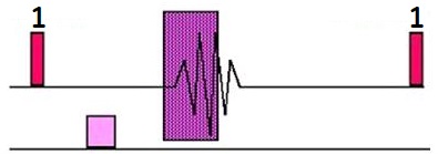
Gated 2D TOF is a Fast GRE pulse sequence designed to reduce pulsatile flow artifact for peripheral MRA exams. This is achieved by synchronizing the data acquisition with the heart rate and segmenting k-space within the cardiac cycle in a manner that optimizes image contrast (makes blood brighter). Gated 2D TOF introduces a new definition for the gating parameter, Delay After Trigger; which is used by the system to determine when the center of k-space is acquired.
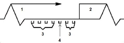
| Number | Description |
|---|---|
| 1 | Trigger delay, peak flow at area of interest |
| 2 | Trigger Window |
| 3 | Outside lines of k-space |
| 4 | Middle lines of k-space |
Use gated 2D Fast TOF to acquire popliteal and carotid artery images
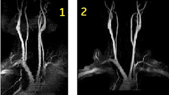
| Number | Description |
|---|---|
| 1 | Standard, non-gated TOF |
| 2 | Gated TOF |
- to reduce artifacts due to pulsatile flow and to acquire aortic bifurcation and iliac images
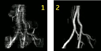
| Number | Description |
|---|---|
| 1 | Standard, non-gated TOF |
| 2 | Gated TOF |
Consider this information when modifying 2D Fast TOF GRE/SPGR scan parameters. For specific scan parameter values, select a protocol from your GE or Site library.
- Scan selections: 2D mode, Vascular family, Fast TOF-GRE or Fast TOF-SPGR pulse.
- Type 2dtofx in the Psd Name field to use a TOF pulse sequence with optimized SAT thickness and gap to improve background suppression. 2dtofx brings the SAT gap closer to the slice group (1 cm vs 2 cm).
Scan parameters
- Flip angle: Use a lower flip angle for Fast TOF GRE and a higher flip angle for Fast TOF SPGR.
- As the flow gets faster, the flip angle may be increased. An increased flip angle increases T1 contrast and SNR.
- Slice order: To optimize flow related enhancement, prescribe the slices from I to S when imaging arterial flow below the heart, and from S to I when imaging above the heart. In other words, prescribe the scans in the direction that is opposite the blood flow.
- Slice spacing: Projection images created by choosing 19 or 37 at the Vascular tab during series prescription appear are distorted or elongated when a slice overlap or gap has been prescribed. To avoid the image distortions, do not use an overlap or gap, or use READY View or Reformat to create the projection images.
- Decreasing the overlap results in decreased scan time since fewer slices are needed to cover the desired anatomy, however, increased partial volume artifacts result as overlap decrease.
- TE: Use the minimum TE for minimal dephasing effects.
- TR: Use the minimum TR to allow the largest number of views per segment, which can reduce the scan time.
- TI: If the IR-Prepared Imaging Option is selected, select a TI value, typically 500 to 600.
- VPS: If the number of VPS results in the available imaging time being exceeded, a message posts, which directs you to reduce the number of Views Per Segment or shorten the Trigger Window.
Imaging Options
- IR-Prepared: If it is selected with a non-gated Fast TOF GRE/SPGR, you cannot select projection images. Projection and vascular images are not generated because abdominal imaging is the intended application for IR-Prepared with Fast TOF GRE/SPGR.
User CVs
Click the Advance tab to view the available User CVs. The CVs may vary based on the field strength and selected scan and imaging parameters.
- Apodization Level
- SAT Gap
- A solution to the retrograde flow artifact is to increase the SAT Gap, which moves the SAT pulse farther away from the slice. As the SAT gap increases, the ghosting from retrograde flow decreases, but so do the fat suppression effects. Typically, a SAT gap greater than 10 mm is only used in areas where there is strong pulsatile flow, for example in the popliteal vessels.
- Use a SAT Gap = 10 mm (carotid and iliac vessel exams) or 20 mm (distal femoral and popliteal vessel exams).
- Increase the SAT Gap as the area to be scanned gets farther away from the heart.
- Increase the SAT Gap and the fat suppression and the retrograde flow artifacts decrease.