

- 00000018WIA3057C770GYZ
- id_400258151.2
- May 26, 2022 4:26:20 AM
TOF tab
The Vascular TOF tab only appears if the protocol is a TOF pulse sequence. Only the vascular selections that are compatible with the active protocol display on the Vascular tab.
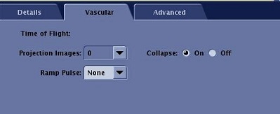
| Item | Description |
|---|---|
| Projection Images | Choose the desired number of Projection Images or leave this blank and create projection images in IVI. |
| Collapse | Collapse reconstructs a collapsed view in the plane of acquisition. |
| Ramp Pulse | See below. |
Ramp Pulse
Ramp Pulse uses a variable flip angle over the imaging volume to reduce saturation of incoming flow. Ramped flip angle excitation combines the benefits of custom-designed, minimum-phase RF pulses with the flow selectivity and increased background suppression of larger flip angles.
- A ramped flip angle excitation pulse with slope 2 has a flip angle that doubles from entry to exit slice. The pulse center flip angle is prescribed; the entry and exit slice flip angles are 2/3 and 4/3 of the center flip angle, respectively. Spatially-varying excitation flip angles prevents saturation of slowly-flowing blood at the entry (low flip angle) part of the slab and provides suppression of venous flow with the large flip angle (exit) portion of the slab. These effects allow improved visualization of slow, in-plane, and tortuous flow, and eliminate the need for a spatial presaturation pulse to cancel venous blood signal.
Figure 2. Example using a 30° flip angle ramped RF pulse 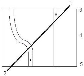
Table 1. Ramp Pulse image legend Item Description 1 40° RF pulse [30 + (1/3 x 30) = 40] 2 20° RF pulse [30 - (1/3/ x 30) = 20] 3 Slice number 60 with a 40° flip angle 4 Slice number 30 with a 30° flip angle 5 Slice number 1 with a 20° flip angle - Do not use Ramp Pulse when the flip angle in your protocol is between 46 and 90. In general, choose flip angles in the 20 to 45° range with Ramp Pulses.
- 3D TOF is less sensitive to flow, which may become saturated as it passes through the imaging volume. The use of Ramp Pulses can offset some of this saturation.
- Ramp Pulses produce images with a variation in background suppression from entry to exit slice and flow speed selectivity as a function of location within the slab.
- Slab boundary artifacts are more prominent with Ramp Pulses.
- Ramp Pulses and Magnetization Transfer (in head) increase small intracranial vessel conspicuity when combined with a high-resolution acquisition.
- Ramp Pulse offers the following image quality improvements:
- Improved slab profile by reducing wrap and improving image quality away from the center of the slab
- Reduced saturation of blood flow increasing the visibility of arteries
- Reduced sensitivity to venous signal
- Shortened minimum TE
- The table below can help you determine the ramp pulse direction, depending on the direction of the blood flow and whether you need to see bright blood or dark blood.
Table 2. Ramp Pulse direction Ramped Pulse direction Blood flow direction Signal intensity I-S I-S Bright I-S S-I Dark S-I I-S Dark S-I S-I Bright - Select the Ramp Pulse flow direction based on the scan plane selected. Refer to the following table for guidance.
Table 3. Ramp Pulse direction based on scan plane selection Scan plane Ramped Pulse direction Blood flow direction Axial I to S Flow and S to I Flow Head Coil Axial I to S Flow is defaulted on Sagittal I to S Flow and S to I Flow Coronal P to A Flow and A to P Flow