

- 00000018WIA30A56970GYZ
- id_400256011.1
- Feb 24, 2022 5:25:47 PM
Inhance: Inflow scan
Inhance Inflow is a contrast-free technique based on the gated 2D Fast GRE PSD. Inhance Inflow is designed to acquire angiography images of arteries that flow in a relatively straight line such as the femoral, popliteal and carotid arteries. It acquires data during the cardiac systolic phase when arterial blood flow is faster in comparison to blood flow during the diastolic phase.
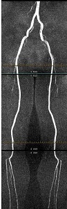
Use Inhance Inflow to acquire a non-contrast angiography images of arteries that flow in a relatively straight line such as the femoral, popliteal and carotid arteries.
For specific scan parameter values, select a protocol from your GE or Site library.
- Scan selections: 2D mode, Vascular family, Inhance Inflow pulse.
- DISDAQs (additional RF pulses) that occur during cardiac segment inactive time, are used to improve background suppression.
General
- For a carotid or run-off scan session, acquire a 3-Plane localizer during expiration.
- Phase encode blurring is expected with Inhance Inflow, as with any cardiac imaging technique. This is because the phase encode lines are acquired during the systolic phase where the vessel pulsatility is maximum in addition to the velocity of blood flow changes during each phase encode acquisition. There are a two ways in which the blurring can be minimized.
- Reduce the VPS to 32 or lower, at the expense of an increase in scan time.
- Use ECG rather than Peripheral gating. With a PG acquisition, only half of the systolic phase is available to leverage TOF effects (minimum TD is already in the middle of the systolic phase). However, with ECG, both halves of the systolic phase are available and this may help to minimize blurring.
Scan Parameters
- Typical Peripheral gating parameters include:
- Trigger Window: Set it to 10% if the heart rate is stable and to 20% of the heart rate has a lot of variation.
- Trigger Delay; Set it to Minimum.
- Views per Segment The value is typically set to 36.
- Projected Heart Rate: It can be entered if the gating signal is not optimum and the waveform is fluctuating, although sub optimal results are typical.
- Graphic Rx: Prescribe the slices from inferior to superior for runoff scans and superior to inferior for carotid scans to avoid saturation of blood. Spatial Saturation should not be prescribed graphically or explicitly to make it concatenated.
Figure 2. InHance Inflow Graphic Rx 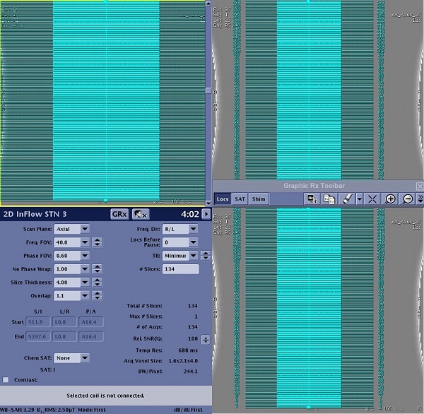
- Phase FOV: Use a Phase FOV less than 1 to reduce scan.
- SAT: For carotid scans select a Superior SAT pulse and for arterial runoff scans when acquiring data from inferior to superior, select an Inferior SAT pulse.
- Slice thickness: Flow velocity and slice thickness are interconnected. Select a thicker slice for higher velocities if spatial resolution is not critical. The slice thickness for the lower leg station is 3 (with overlap of 1.1) and 4 (with overlap of 1.1) for the upper stations. This variation in slice thickness is to accommodate change in vascular flow and SNR from one station to the next.
Imaging Options
- ASSET: Select ASSET.
- ASSET is used to shorten the scan time.
- An ASSET compatible coil must be selected for ASSET to be available as an Imaging Option.
- Typically use the default ASSET acceleration factor.
- If any or all of these scan parameters are selected (ASSET, HyperBand, PURE), and if you select On from the Calibration in Prescan menu, which is located on the Details tab, a calibration scan is acquired during Auto Prescan.
User CVs
Click the Advance tab to view the available User CVs. The CVs may vary based on the field strength and selected scan and imaging parameters.
- Optimized SATgap for SLIP
- SAT Gap
- SAT Playout
- 0 for arterial scans and 1 for venous scans.