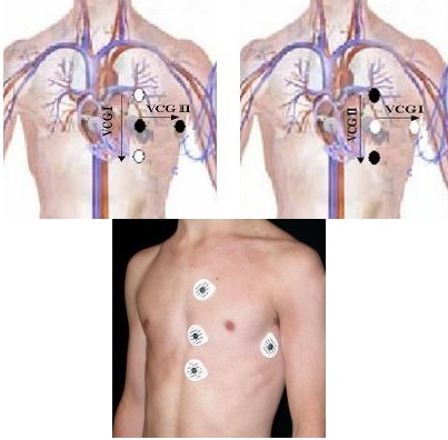
Connect the electrodes to the black and white lead pairs that are marked by a color bead located near the connector. The leads are color coded, but also have a color center stud on the wire near the connector. The leads should be connected as orthogonal pairs as shown in the image below. They can be in any direction as long as the pairs are orthogonal.
white lead: white stud
red lead: white stud
green lead: black stud
black lead: black stud Figure 1. Vector electrode placement: arrows represent Vector 1 or 2, as long as the pairs are orthogonal.
In the footer area, click the to open the Gating Control screen.
Click Cardiac Gating.
For wired gating, click Independent Vector Gating.
Both waveforms are displayed on the Waveform screen.
Confirm that the waveforms are acceptable. Adjust electrode placement, if necessary.
Advance the patient to the scan location.
Select Gating Reset to clear the triggering history and relearn the patient’s waveforms.
Do this before scanning when the patient is at the scan position and the waveforms are free of interferences.


 to open the Gating Control screen.