Use these steps to create an axis of symmetry of the anatomy, deposit an ROI on one side of the anatomy, and then propagate the ROI to the exact same location on the other side of the anatomy. This is useful when you want to compare ROI statistics from two locations on either side of an axis of symmetry, for example, left and right side of the brain.
Step-by-step instructions
Launch a READY View protocol that has a Mirror ROI Review Step, such as ADC or BrainStat.
From the Review Step panel, select the Mirror ROI Review Step.
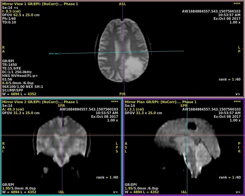
Adjust the line cursors so that the vertical and horizontal lines create orthogonal sagittal and coronal images, thus creating an axis of symmetry where the left side mirrors the right side.
Adjust the horizontal and vertical cursors on any of the three images.
Select the cross section/cross hairs to move the entire line Left-to-Right, Superior-to-Inferior, or Anterior-to-Posterior.
Select the outer edges of the cross hairs to rotate it.
Image prior to correction - head is tilted indicated by the horizontal and vertical lines do not create orthogonal coronal and sagittal images Figure 1. Mirror ROI adjusting axis of symmetry
From the Mirror Plane screen, click Lock Plane.
The Vertical and horizontal lines indicate the correction. Note that you can move the dotted lines on the sagittal or coronal views to change the axial view thickness.
If you need to readjust the axis of symmetry, click Reset Plane, adjust the horizontal or vertical cursors and click Lock Plane to reset the axis of symmetry.
The symmetry plane will be kept in memory even if you select another Review Step.
The Mirror ROI button is available from any review step once the symmetry plane is defined and validated.
The symmetry plane will be restored by a Save State.
Deposit an ROI.
3D Box Area is not available for the Mirror ROI feature.
From the Tools area, click Measure/annotate tool panel.
Select an ROI (2D ROI, 3D sphere ROI, Free-hand ROI, Auto-contour ROI). A 3D ROI is recommended (3D Sphere or Autocontour).
Place the cursor in an image viewport and left-click to deposit the ROI.
From another Review Step, Mirror ROI will be visible once the plane is switched to Oblique plane.
Adjust the ROI size and shape.
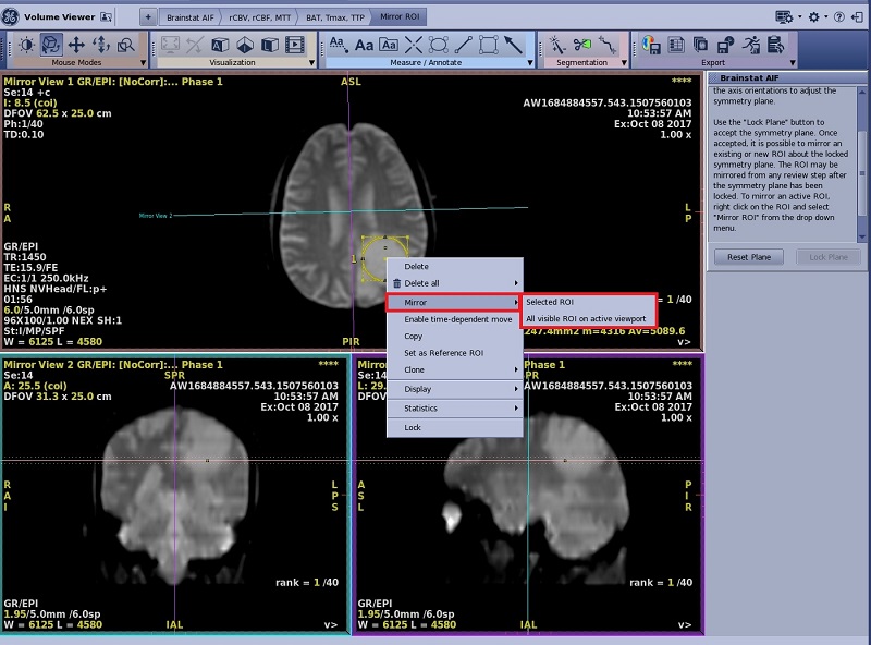
Place the cursor over the ROI, right-click and select Mirror > Selected ROI or Mirror > All Visible ROI on active viewport.
Figure 2. Mirror ROI from menu
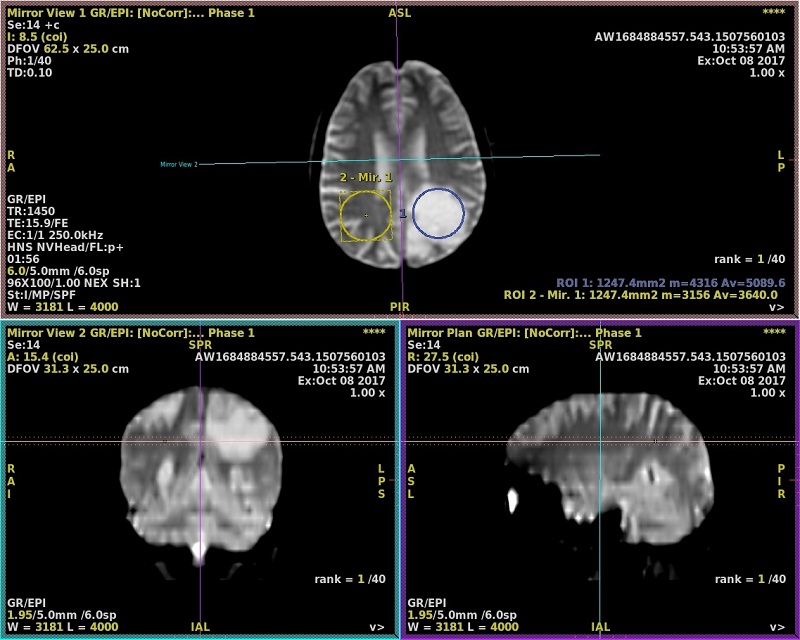
The ROI is deposited in both halves. Figure 3. Mirror ROIs are deposited
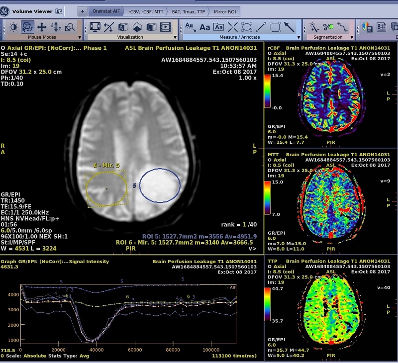
From another Review Step, Mirror ROI is visible in any plane in the upper left hand corner image and the ROI is active.
Figure 4. Another review step is selected and the mirror ROI appears on the image in the upper left viewport
If in the FiberTrak workflow, from the FiberTrak Review Step, click Mirror Fiber to trigger tract computation from Mirror ROI.
Optional: for a BrainStat protocol, change one of the viewports to a graph view to display the time/intensity curves.
In order for the Graph view type to appear as an option, first change the yellow series type/map annotation to a series type and then click the yellow image plane annotation. Graph is a selection in the menu.
Optional: From the Export Toolbar, click the Summary Table icon () to view the Summary Table screen and to view a table of the ROI statistics and to propagate the mirror measurements into the Summary Table.


 ) to view the Summary Table screen and to view a table of the ROI statistics and to propagate the mirror measurements into the Summary Table.