

- 00000018WIA30428870GYZ
- id_400217271.3
- Apr 13, 2022 2:45:35 AM
Truncation artifact
The truncation artifact may appear when k-space data is not completely acquired. This artifact appears around bright tissue and spreads along the partial k-space direction. It is enhanced if the brightness changes sharply along this direction.
To reduce this artifact, change your protocol to include one or more of the following:
- Reduce the FOV to avoid sharp contrast changes.
- Increase the matrix values to 256 x 256 or 512 x 512 to apply full k-space data acquisition.
- Change the TE value to MinFull if Minimum is used.
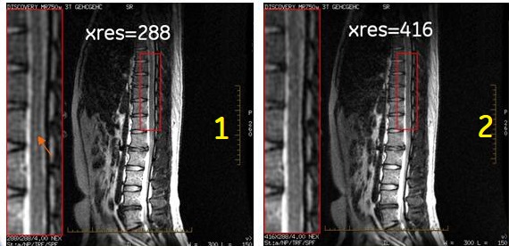
| Number | Description |
|---|---|
| 1 |
Note: The bright signal/truncation artifact in the spinal column. The image was acquired with the following parameters:
|
| 2 |
Note: The truncation artifact is no longer present. All scan parameters are the same except the following:
|