

- 00000018WIA301DE770GYZ
- id_400216571.12
- Sep 6, 2022 4:26:37 AM
Set up the peripheral gated exam
About this task
The peripheral gating connector is a Type BF applied part.
Note: GE uses a method called photo-plethysmography (PPG) for the peripheral gating. The acronyms PG and PPG may be used interchangeably.
Use these steps to set up a peripheral gated scan and to attach the sensor to the patient. Use peripheral gating during head or cervical/thoracic spine imaging to minimize pulsatile motion of CSF on T2 or T2* scans.
Note: Ensure that the anatomy where the sensor is placed remains cool and dry during the entire exam.
| Warning | |
|---|---|
Step-by-step instructions
- Open the Gating Control screen.
- In the header area, click the Tools icon (
 ) to open the System Management work area. Click the Gating/Fan/Light tab to open the Gating Control screen.
 - Alternatively, in the footer area, click the Hardware icon (
 ). Click the Gating tab to open the Gating Control screen.
- In the header area, click the Tools icon (
- Attach the sensor to a toe or finger with minimal callous to ensure a good reading.The best location for a finger sensor is the back edge of the middle finger nail of the patient's dominant hand. Put the probe between the tip of the finger and the distal joint, but not on a joint or knuckle.Note: Do not use the same arm for PG as has the blood pressure cuff. The PG triggering stops when the blood pressure cuff is inflated.
Figure 1. Wired peripheral gating sensor attached to finger 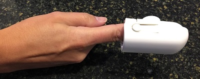
To apply the sensor, gently squeeze the finger band at its widest point. Put the finger band on the patient's finger so that the emitter button (LED) is on top of the patient's fingernail.