

- 00000018WIA30348970GYZ
- id_400225791.3
- Jul 3, 2022 5:47:12 PM
BrainStat AIF Optional procedure
About this task
To change BrainStat settings, make a selection from the desired BrainStat AIF screens.
Step-by-step instructions
- From the BrainStat AIF screen, click the preprocessing arrow and click Motion Correction if the images exhibit distortions with respect to the reference image.
- Use the Scoll Image icon (
 ) on the Review Controller to review all the input images for motion artifact or incorrect geometry before processing.
 - Use Motion Correction to minimize the effects of patient motion.
- To save the new set of processed images so that you can access the corrected series repeatedly, click Quick Export on the export toolbar.
- Use the Scoll Image icon (
- From the BrainState AIF screen, click the AIF mode arrow and click one of the processing modes.
- Ensure recomputation of maps after modification of input parameters.
- Ensure that you review and if necessary correct the position and signal characteristics of detected vessels in automatic and semi-automatic mode before reviewing the computed functional maps. Switch to a different vessel detection mode if results are not optimal.
- Auto is the default option. It automatically selects pixels based on the temporal form of the signal. After AIF pixels have been determined, all pixel values are averaged and a final AIF curve displays.
- Click Semi-Autoto search for arteries within a user defined ROI.
- From the Measure/Annotate toolbar, click an ROI tool.
- Click the image to deposit the ROI.
- Position and shape the ROI. For details, see Modify measurements.
- From the AIF Mode selection area, click Search to activate the detection of arteries within the ROI.
- Click Compute to update the maps.
- Click Manual to define one single-pixel artery. From the Manual AIF mode area, complete the following:
- Click the Pixel ROI icon (
 ).
). - Left-click in the area of interest to deposit the pixel ROI.
- Click Compute.
- Click the Pixel ROI icon (
- Be sure to place manual vessel pixels in appropriate areas of the image based on anatomy and signal characteristics.
- Auto, Semi-auto and Manual arteries can be deleted by selecting the individual artery and pressing Delete. Alternatively, right-click a vessel and select Delete or Delete All from the menu.
- From the BrainStat AIF screen title bar, click the Tools icon (
 ).
). - To view leakage indicator for functional curves, complete these steps.
- From the Review steps, click the rCBV, rCBF, Leakage tab (
 ).
). - Place the cursor in the graph viewport and right-click to display the Graph Curves Selection screen.
- From the Graph Curves Selection screen, click the Reconvolved Signal option button, which displays either a T1 or a T2* effect graph and map.
Figure 1. Graph Curves Selection screen 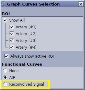
Figure 2. T2* Leakage Indicator graph and map 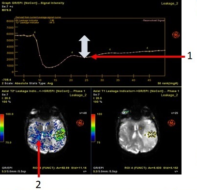
Table 1. Image legend Number Description 1 T2* Leakage Indicator graph shows where the post-bolus stays below the baseline level. 2 T2* Leakage Indicator map. Figure 3. T1 Leakage Indicator graph and map 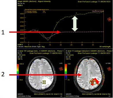
Table 2. Image legend Number Description 1 T1 Leakage Indicator graph shows where the post-bolus curve crosses above the baseline level. 2 T1 Leakage Indicator map.
- From the Review steps, click the rCBV, rCBF, Leakage tab (
- To exit READY View, click the Exit icon (
 ).
).