

- 00000018WIA301BA870GYZ
- id_400251071.2
- Feb 9, 2022 9:16:13 AM
Link series
About this task
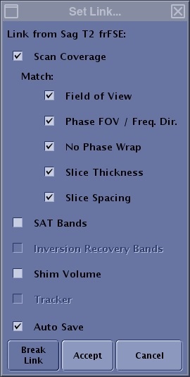
| Parameter | Description |
|---|---|
| Scan Coverage | Matches the scan coverage between the linked series. Note that if the selected series does not support the scan coverage option, it is not selectable. |
| Match | Matches the selected options of Frequency FOV, Phase FOV/Freq Dir, No Phase Wrap, slice thickness and spacing between the linked series. |
| SAT Bands | Matches the SAT bands between the linked series. |
| Inversion Recovery Bands | Matches the IR bands between the linked series. |
| Shim Volume | Matches the shim volume between the linked series. |
| Tracker | Matches the tracker between linked series. |
| Auto save | When Auto Save is selected and the first series has been Setup and Save Rx is selected, then the linked series is automatically changed to an RXD state. This means that you can simply select the series and click Scan to initiate the acquisition on the linked series or the scan will automatically start if Auto Scan is on. |
| Break Link | Breaks the link between selected series. |
| Accept/Cancel | Accepts the Set Links selections. Cancel closes the Set Links screen without applying the selections. |
You can link the following:
- A source task that supplies parameter values to a destination task.
- A destination task that receives parameter values from a source task.
- A task link which is a link between two tasks. It exists because of one or more parameters have been linked between the tasks.
- A parameter link that is linked between two tasks.
- Once a link has been created, the link column displays the series representing the linkage.
Linking allows you to link scan coverage, SAT bands, shim volume, and scan range parameters from one series to another if the series meet the following criteria: orthogonal to matching orthogonal (axial to axial), orthogonal to oblique, multi-slab to single slab, etc. Linking is
- Multiple series (secondary tasks) can be linked to a primary series.
- Links are created in a downward fashion on the Workflow Manager. For example, if you want to link tasks to series 4 (the primary task), only series 4+ (secondary tasks) can be linked to series 4 and series 1-3 cannot be linked to series 4.
- Linked secondary tasks are annotated with the primary task number.
Figure 2. In this example, series 5 and 6 are linked to series 4 and series 9 is linked to series 8 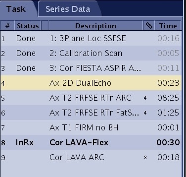
- After a link is created, if you copy/paste the source series, a prompt displays. Since you have 2 potential source series, choose one of the two as the source series: Redirect or Retain, or click Break to break the link.
Figure 3. Paste Linked Series screen 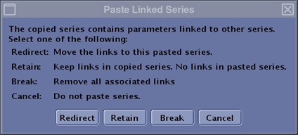
Step-by-step instructions
- Start a scan session.
- To link series together, follow these steps.
- Select the active scan session tab.
- From the workflow manager, click a series on the Task tab.The first series selected can be in any state.
- Press Ctrl and simultaneously click additional link compatible series.
- orthogonal to matching orthogonal
- axial to axial, sagittal to sagittal, coronal to coronal
- orthogonal to oblique
- multi-slab to single slab
- All series selected have a yellow background.
- Place the cursor in the task list and right-click to open the Edit menu.
Figure 4. Edit menu 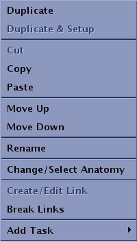
- You can also click .
- From the Set Link screen, click the desired options.
- If a parameter is incompatible with all the destination series, then it is grayed out.
- If a parameter is incompatible with part of the destination tasks, then it is enabled but displayed with italic font. Italic font only appears when you have linked two or more secondary series to a primary series.
- In the following image, the screen demonstrates the following scenario. If you are trying to create a link from Ax T1 FLAIR to Ax T2 PROPELLER, Ax T2 FLAIR and Ax T1 SE, the “Phase FOV/Freq. Dir” is in italic since Ax T2 PROPELLER doesn’t support it but the other 2 destination tasks support it.
Figure 5. Set Link example with different parameter compatibilities 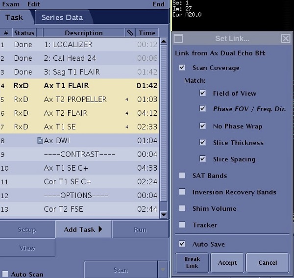
- Click Accept.
- The series to which it is linked appears in the chain link column.
- Series that are linked with all scan parameters completed display the state as RxD once you click Save Rx.
- Series that are linked but are missing a scan parameter display the link but the series do not go to the RxD state. This happens when the secondary series are from a PSD that has scan parameters that the primary series PSD does not have.
Figure 6. In this example, series 8, 9 and 10 are missing the Refocus Flip Angle parameter and thus cannot be in the RxD state 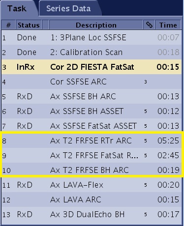
- To edit a link, follow these steps.
- From the workflow manager, click a series from the Task tab that displays a number in the chain link column.
- Adjusting any of the linked series individually breaks the link.
- You may frequently have multiple links in the Task workflow manager if you selected a series as the source and then linked it to other series one at a time. Each of these other series are destination links to the source link. To edit these links, you must select the destination series. In the following image, there are four linked series where the top series (Ax FSE T2) is the source series. Create/Edit Link option is not available on the Edit menu for the source series since the system would not know which link is to be edited.
Figure 7. Four linked series 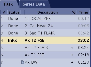
- In this image, series 4 is linked to series 5, 6 and 7, and series 3 is linked to 8 and 10.
Figure 8. Modified links 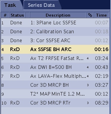
- In this image, series 4 is linked to series 5, 6 and 7, and series 3 is linked to 8 and 10.
- You can Create/Edit any of the series, if you Edit the source series all linked series will update.
- If you Create/Edit a linked series it will no longer be linked to the source series.
- Place the cursor in the task list and right-click to open the Edit menu.
- You can also click .
- From the Set Link screen, edit the desired options.
- Click Accept.
- From the workflow manager, click a series from the Task tab that displays a number in the chain link column.
- To break a link, follow these steps.
- From the workflow manager, click a series on the Task tab that displays a link.
Figure 9. Link Column 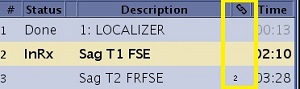
- The first series selected can be in any state.
- You can also place the cursor in the task list and right-click to open the Edit menu.
- Click Break Links.
- The chain links next to the series are removed.
- Note that the link is broken when The Phase FOV or Frequency Direction are changed if Phase FOV or Frequency Direction are linked.
- A link is broken when you explicitly change a parameter on the destination task that invalidates the link. For example, if you selected the FOV option box on the Set Link screen, and then you edit the destination series and change the FOV, you have just broken the link. You can change parameters on the destination series that are not on the Set Link screen, for example TR, and the link remains in tact.
- From the workflow manager, click a series on the Task tab that displays a link.