

- 00000018WIA30803970GYZ
- id_400265941.4
- Aug 21, 2022 3:58:45 PM
Spin Echo
Spin Echo is a 2D pulse sequence that consists of a 90° excitation pulse, spatial encoding, a 180° refocusing pulse, and signal readout.
Consider this information when modifying a Spin Echo scan parameter. For specific scan parameter values, select a protocol from your GE or Site library.
Number of echoes
With Spin Echo, either one, two, or four echoes can be acquired within a single acquisition. Variable or two-echo allows the second echo to be a non-multiple of the first echo, e.g., TE1 = 14 ms and TE2 = 95 ms. A four-echo acquisition results in four images where each image represents a TE that is a multiple of the first echo, e.g., TE 20 results in four images acquired at the following TE times: 20, 40, 60, and 80 ms.
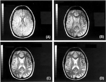
Each echo is used to create a different image, usually displaying different image contrast. The images below were acquired using a Spin Echo variable echo sequence. The first echo displays PD-weighting, while the second echo displays T2-weighting.
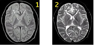
| Number | Description |
|---|---|
| 1 | First echo |
| 2 | Second echo |
Image characteristics
Spin Echo images are generally less sensitive to magnetic field inhomogeneties and paramagnetics than most other pulse sequences. This is due to the RF rephasing of protons. Less geometric blurring is seen on Spin Echo images in comparison to FSE images, therefore producing sharper image edges. When comparing Spin Echo images with FSE images, longer scan times for sequences with the same TR values are seen.
Image contrast
| Timing | PD weighting | T2 weighting | T1* weigting |
|---|---|---|---|
| TR | Long > 2000 ms | Long > 2000 ms | Short < 800 ms |
| TE | Short < 30 ms | Long > 90 ms | Short < 25 ms |
| As field strength decreases, TR and TE decrease. | |||
T1 is the time constant for longitudinal relaxation and thermal or spin lattice relaxation. Scan protocols that allow the T1 effects to predominate over the other relaxation effects produce T1-weighted images. In T1-weighted images, tissues with short T1 are bright and tissues with long T1 are dark. In the brain, white matter is brighter than gray matter, and CSF is dark.
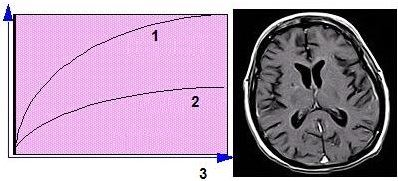
| Number | Description |
|---|---|
| 1 | Short T1 (fat) |
| 2 | Long T1 (water) |
| 3 | Time or TR period |
T1-weighted images cannot be produced in conjunction with PD-weighted or T2-weighted images, because the TR requirements are not compatible.
T2 is the time constant that measures the transverse magnetization decay and spin-spin effects. Scan protocols that allow the T2 effects to predominate over the other contrast effects produce T2-weighted images. In T2-weighted images, tissues with short T2 are dark and tissues with long T2 are bright. In the brain, CSF produces the brightest signal on moderate to late TE images; pathology that alters and delays T2 also appear bright.
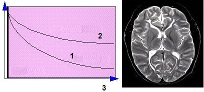
| Number | Description |
|---|---|
| 1 | Short T2 (fat) |
| 2 | Long T2 (water) |
| 3 | Time or TE period |
PD-weighted images have contrast that is primarily due to the density of protons in the structures. PD-weighted images result when you select scan timing parameters that minimize the T1 (long TR) and the T2 (short TE) contrast effects. With PD-weighted images, tissues with a greater number of protons are bright and tissues with fewer protons are dark. In the brain, gray matter is brighter than white matter, due to the amount of protons it contains.
PD- and T2-weighted images can be produced in the same acquisition using two echoes because the TR requirements are compatible.
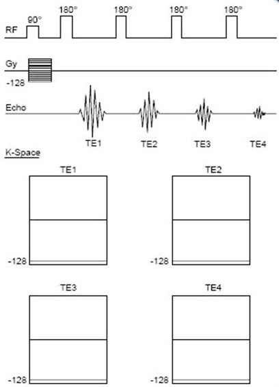
K-space
In conventional Spin Echo imaging, the phase encoding gradient is applied only once, even if two or four echoes are being generated. Each echo possesses the same phase encoding but, as each echo (TE1, TE2, TE3, TE4) is sampled, the sampled data contribute to a separate image. In other words, a two- or four-echo Spin Echo may provide two or four lines of k-space per TR, but each line of data is placed in a separate k-space for that particular image.
For example, if a TR of 2000 ms, a 256×256 matrix, a TE of 15 ms, and four echoes were chosen, the result would be: at time TR the 90° pulse would be applied, phase encode gradient -128 would be applied and then four 180° pulses would be applied. Each of these would produce an echo and be accompanied by a readout gradient. Since only one line of k-space is filled at a time, the experiment is repeated 255 more times (256 lines/1 line-TR interval = 256 TR intervals). The associated scan time is 2 sec × 256 repetitions × 1 NEX = 8:53 or 8.32.
Spin Echo scan considerations
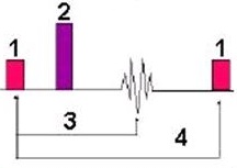
Spin Echo is a 2D sequence consisting of a 90° excitation pulse followed by at least one 180° refocusing pulse. The 90° pulse creates magnetization in the transverse plane, and the 180° pulse rephases the magnetization to produce spin echo signals.
With Spin Echo, either one, two, or four echoes can be acquired within a single acquisition. Spin Echo is used to acquire images with T1-, Proton Density-, or T2-weighted contrast.
| Number | Description |
|---|---|
| 1 | 90° |
| 2 | 180° |
| 3 | TE |
| 4 | TR |
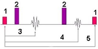
Variable echo is a two-echo acquisition where the second echo does not have to be a multiple of the first echo (e.g., TE1 = 20 ms, TE2 = 90 ms).
| Number | Description |
|---|---|
| 1 | 90° |
| 2 | 180° |
| 3 | TE1 |
| 4 | TE2 |
| 5 | TR |
Use Spin Echo sequences to acquire images with T1-, PD-, or T2- weighted contrast in all anatomical areas.
Consider this information when modifying Spin Echo scan parameters. For specific scan parameter values, select a protocol from your GE or Site library.
- Scan selections: 2D Mode, Spin Echo family, Spin Echo pulse.
Scan Parameters
- The effects of changing TR and TE on PD/T2 images:
- The effect of changing TR and TE on T1 images:
- As TR increases, CNR decreases, SNR, Scan Time, and the number of slices increase.
- As TE increases, CNR, SNR, and the number of slices decrease, while scan time remains constant.
- The effects of changing Flip Angle on T1 contrast:
- As the flip angle increases with a TR > 600, the T1 contrast increases.
- Type t1memp in the PSD Name field if you want to adjust the flip angle.
User CVs
Click the Advance tab to view the available User CVs. The CVs may vary based on the field strength and selected scan and imaging parameters.
- Apodization Level
- Dynamic TG
- MT Frequency Offset
- PURE compensation
- Spatial Sat Type
- SAR Optimization
- TR Range for Auto TR, for details see Auto TR.