

- 00000018WIA30AEF870GYZ
- id_400257641.1
- Feb 24, 2022 5:58:48 PM
Inhance: 3D Inflow IR scan
This sequence is based on 3D FIESTA, which improves SNR and produces bright blood images. Selective inversion pulses are applied over the region of interest to invert arterial, venous, and static tissue. At the null point of the background tissue, an excitation pulse is applied to generate signal. The net result is an angiographic image with excellent background suppression and free of venous contamination. Inhance Inflow IR can also be used to image venous vasculature. This can be achieved by setting inversion recovery pulses to suppress upstream arterial flow.
Use Inhance 3D Inflow IR to acquire contrast-free angiographic images with excellent background suppression that are free of venous contamination. Inhance Inflow IR can also be used to image venous vasculature. This can be achieved by placing IR bands to suppress upstream arterial flow.
Consider this information when modifying InHance 3D Inflow IR scan parameters. For specific scan parameter values, select a protocol from your GE or Site library.
| Warning | |
|---|---|
- Scan selections: 3D mode, Vascular family, Inhance IFIR pulse.
General
- Position the patient Supine, Feet First.
- Typically, use a body array coil.
- Acquire a 3-Plane localizer during expiration.
- If any or all of these scan parameters are selected (ASSET, HyperBand, PURE), and if you select On from the Calibration in Prescan menu, which is located on the Details tab, a calibration scan is acquired during Auto Prescan.
Scan Parameters
- Auto IR Band On/Off is selected from the scan Details tab.
- Turn it On for axial scans.
- Turn it Off for non-axial scans and to manually apply IR SAT bands on sagittal, coronal and oblique scans. Save Rx is disabled until you place the IR SAT bands.
BSP TI: Typically BSP TI = 1200. BSP TI has an effect on background suppression as well as venous suppression. You can select a range between 1000-1800 ms.
SAT: Select SPECIAL as a chemical SAT option.
Imaging Options
Respiratory triggering: Patient respiration is critical. From the Respiratory tab consider the following:- Use respiratory gating to reduce respiratory motion artifacts. Attach the respiratory bellow where the maximum respiratory movement is observed and instruct the patient to breath consistently.
- Trigger point : Select or enter a Trigger Point value between 10 and 50%, (optimum is 10%) which is the point in the respiratory cycle when imaging will begin. The goal is to set the trigger point and window so that the imaging window occurs at the quiescent portion of the breathing cycle.
- Number of R-R interval: defines the Effective TR. Typically select 1 R-R interval.
- Set the phase FOV to 1 for larger patients.
- Use the Phase acceleration factor of 2.00.
Graphic Rx
- Slab: Graphically deposit and position a single slab.
- Position the slab volume to cover both renal arteries. Acquire localizer and ASSET cal in expiration as the InHance 3D Inflow IR acquisition is done with respiratory gating during expiration.
- If Auto IR Band is selected with axial scans, a selective prep inversion volume is automatically applied by the system. It is not shown graphically.
Figure 2. Prep and acquisition volumes 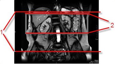
Table 1. Prep and Acquisition volumes image legend Number Description 1 Prep volume 2 Acquisition volume
- Prescribe IR volume if the scan plane is non-axial and you selected Off for Auto IR Band, which means that you are manually determining the IR volume. The prescribed position of the prep inversion volume is critical for InHance 3D Inflow IR image quality. To maximize the in-flow effect, set IR Band close to the organ that you want to visualize. For renal artery images, placing the inversion volume too far superior may suppress artery signal and thus reduce the image SNR. Placing the inversion volume too far inferior may cause artifacts due to in-sufficient background suppression.
- Complete these steps to place the IR bands.
- From the Graphic Rx Toolbar, click IR.
- Click IR A.
- The default thickness is automatically displayed. Place the cursor in the Thickness text field and type a new thickness if desired.
- Place the cursor on the localizer image and click to deposit the IR volume.
- Click and drag the IR volume to adjust the location and angle.
- Click IR B and repeat steps 3-6.
Figure 3. Inhance Inflow IR localizer with IR SAT bands 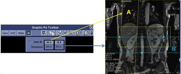
Other SAT pulse placements to image a variety of vessels
- Renal arteries
Figure 4. Coronal localizer with IR band and resultant coronal renal image 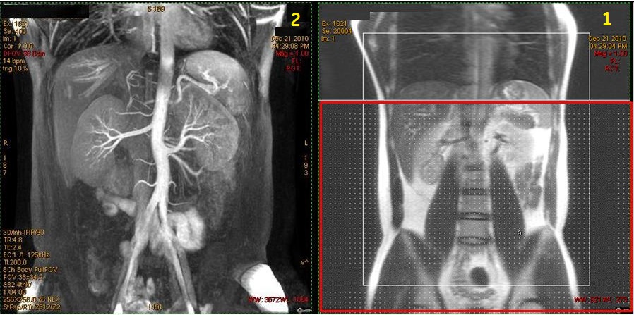
Table 2. Image legend Number Description 1 Coronal localizer with large axial IR band (red box) applied inferior to saturate venous flow. 2 Resultant Inhance Inflow IR coronal image of renal artery . - Liver arteries
Figure 5. Coronal localizer with IR band and resultant coronal liver arteries 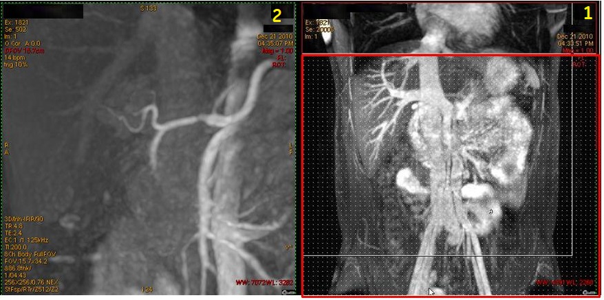
Table 3. Image legend Number Description 1 Coronal localizer with large axial IR band (red box) applied inferior to saturate venous flow. 2 Resultant Inhance Inflow IR magnified coronal image of liver artery. - Portal vein
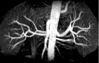
Figure 6. Coronal localizer with two IR bands and resultant coronal liver portal vein 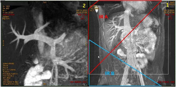
Table 4. Image legend Number Description 1 Coronal localizer with two IR bands applied to saturate arterial flow. 2 Resultant Inhance Inflow IR magnified coronal image of portal vein. - Abdomen with no IR bands showing veins and arteries
Figure 7. Coronal localizer with no IR bands and resultant abdominal veins and arteries 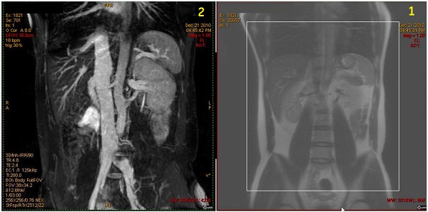
Table 5. Image legend Number Description 1 Coronal localizer with an IR band placed to the right or left well out of the FOV. Do not move the IR band superior or inferior as that will suppress signal from blood. 2 Resultant Inhance Inflow IR coronal image of veins and arteries. - Abdominal veins
Figure 8. Coronal localizer with IR band and resultant coronal abdominal veins 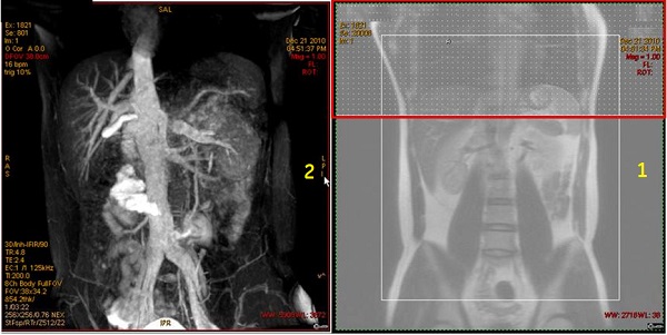
Table 6. Image legend Number Description 1 Coronal localizer with axial IR band (red box) applied over the heart to saturate arterial flow. 2 Resultant Inhance Inflow IR coronal image of abdominal veins. - Carotid arteries
Inhance 3D Inflow IR for carotid imaging works best on 1.5T systems.
Figure 9. Coronal localizer with IR band and resultant coronal carotid image 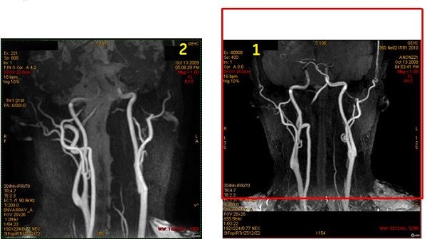
Table 7. Image legend Number Description 1 Coronal localizer with superior axial IR band (red box) applied to saturate venous flow. 2 Resultant Inhance Inflow IR coronal image of carotids. - Pulmonary arteries
Figure 10. Coronal localizer with IR band and resultant coronal pulmonary arteries 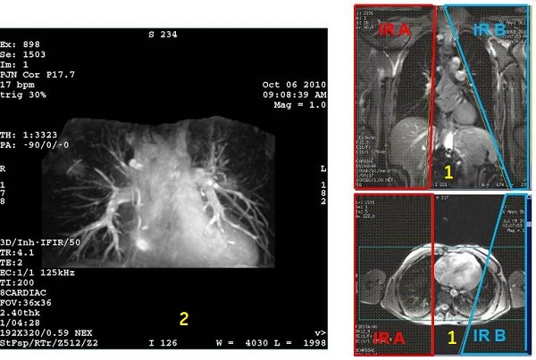
Table 8. Image legend Number Description 1 Top localizer image: Coronal localizer with IR two bands applied over the lungs. Bottom: Axial localizer with two IR bands applied over the lungs.
2 Resultant Inhance Inflow IR coronal image of pulmonary arteries.