

- 00000018WIA30963970GYZ
- id_400248671.5
- Mar 28, 2022 3:41:50 PM
FiberTrak workflow
About this task
Use these steps to generate FiberTrak images. FiberTrak is an optional feature and requires a Diffusion Tensor data set.
Important: In a tractography view, the software computes the gradient of each voxel within the volume in order to compute the voxel’s color and associated shading for the three displayed planes: axial, coronal, and sagittal. The gradient computation requires information from not only the voxel but also its neighboring voxels. To prevent artifacts, the voxels located at the volume borders that have missing neighboring voxels are not displayed. In a tractography view, the first two slices and the last two slices are not rendered in the sagittal and coronal planes, even though some fibers might be found and displayed in those areas.
Step-by-step instructions
- From the Review Steps, click FiberTrak.
Figure 1. Review Steps for FiberTrak protocol 
The colored orientation images display. Consider changing one of the viewports to oblique. Note that as you rotate the cube, the orientation map in the lower right corner updates.
- Click one of the ROI icons from the DTI screen.
Figure 2. FiberTrak ROIs list 
- Position the cursor over the area of interest and click to deposit the ROI. Size and shape the ROI as needed.
- Any image viewport can be used to position the ROI. Typically, use the color orientation map - it is very useful in visualizing the white matter tract orientations.
- If you draw a free hand ROI, select a Propagation mode.
- You can deposit up to 5 ROIs per tract.
- The more ROIs you deposit the longer the computation time.
- To remove a tract or ROI, click the Trash icon (
 ) next to the item you want to remove.
 Figure 3. Example of a tumor segmented using Auto Contour and then fused with fiber tract image and volume rendered 3D image 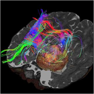
- To toggle the tracks on/off the image, click the Eye icons (
 or
or  ) next to the track. This can be done from either the Fiber Track list screen or from the Multi-Objects screen.
 - From the DTI screen title bar, click the Tools icon (
 ).
). - To exit READY View, click the Exit icon (
 ).
).