A 3D protocol must be selected from the Workflow Manager and be in the INRX (In Prescription) state.
About this task
Use these steps to prescribe a 3D acquisition.
Step-by-step instructions
Place the cursor in the viewport on which you want to deposit the slab.
Click to deposit the first slab.
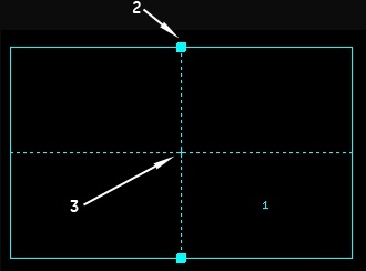
Figure 1. Orthogonal 3D Graphic too
Table 1. Orthogonal 3D Graphic tool image legend
Number
Description
1
Start direction of the 3D slab
2
Add handle, which only appears if the PSD allows multi-slab capability
3
Center of the slab
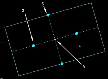
Figure 2. Oblique 3D Graphic Rx tool
Table 2. Oblique 3D Graphic tool image legend
Number
Description
1
Start direction of the 3D slab
2
Rotation handle
3
Center of the slab
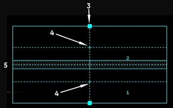
Figure 3. Multi-slab orthogonal 3D Graphic Rx tool with overlap
Table 3. Multi-slab orthogonal 3D Graphic Rx tool image legend
Number
Description
1
Start location of the first 3D slab
2
Start location of the second 3D slab
3
Add handle
4
Center of slab
5
Overlap slice area
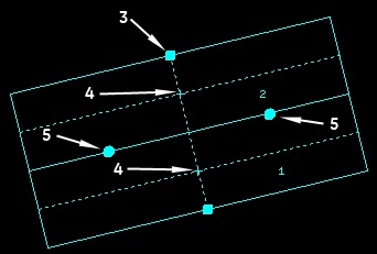
Figure 4. Multi-slab oblique 3D Graphic Rx tool with no overlap
Table 4. Multi-slab oblique 3D Graphic Rx tool image legend
Number
Description
1
Start location of the first 3D slab
2
Start location of the second 3D slab
3
Add handle
4
Center of each slab
5
Rotate handle
Optional: On the 3D graphic tool, click and drag the add handle to add more slabs if the pulse sequence allows multi-slab acquisitions.
Press Shift and simultaneously click for each group of slabs you want to add to the prescription.
Change the scan range parameters (FOV, slice thickness, slice locs/slab) as needed to adjust the Graphic Rx.
If the slice location lines that have been saved in a protocol are orthogonal, when they are applied to the localizer image the slices are applied in the same fashion that they were saved in the protocol.
If the slice location lines that have been saved in a protocol are oblique, when they are applied to the localizer image the slices are applied right to left. The start/end locations change to reflect this state. To obtain a left-right slice prescription that was originally saved in the protocol, the slices must now be rotated (3D or 2D), or erased and prescribed again (2D only).
To select a viewport other than the default viewport, click it to make it active.
You can only tilt the slab if oblique is the selected plane.
When depositing a single slab, the slices are acquired using the LIP rule: sagittal plane acquires left to right, axial plane acquires images inferior to superior, coronal plane acquires images posterior to anterior.
If your 3D slab is orthogonal: click and drag the Add handle to collapse the slab into a single slab, then drag the handle in the opposite direction to acquire the images in the opposite direction of the LIP rule.
If your 3D slab is oblique, then click and drag the rotation handle and twirl the slab around to acquire the images in the opposite direction of the LIP rule.