

- 00000018WIA30530970GYZ
- id_400228101.8
- Jun 21, 2022 8:32:13 AM
Series numbering
About this task
Series numbering in the Patient List depends on the type of imaging application performed. Click an application below for more details or for a quick description of the application series numbering scheme, refer to the table below.
| Application | Created series number | Notes | ||||
|---|---|---|---|---|---|---|
| 3DASL | PW and PD phases are in same series | |||||
| 3DCINE-SPGR 3DCINE-FIESTA | Nx100 | Two series are created: a preview series and a fully reconstructed anatomy cine series.
The series number of the preview series is multiplied by 100 for the full anatomy series. 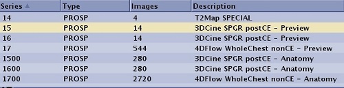 | ||||
| 4DFLOW | N×100*: the anatomy cine series, N×100+1*: the LR flow cine series N ×100+2*: the AP flow cine series N ×100+3*: the SI flow cine series | The 4DFLOW series numbering is the number of the preview series multiplied by 100 for the fully reconstructed anatomy series and multiplied by 100 plus 1, 2 and 3 for the Left-Right, Anterior-Posterior and Superior-Inferior flow series, respectively. 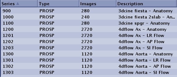 | ||||
| Post Process
ClariView MRA READY View AddSub Collapse Projection Pasting | N</=99 N*100+I
N>99 N+I | I=0..n (use first empty series)
I=1..n (use first empty series) For image pasting N is the lowest numbered series in the input data set. | ||||
| Auto Subtract | N*100
N+10,000 | N < 100
N >/= 100 | ||||
| DTI | N*100, N*100+1, N*100+2 | Each group (CMB, T2, direction 1, direction 2,...) has all slices in the order of slice location.
T2 and all diffusion images are in a single series. Given the order of groups and slices, the image number will start from 1 and end as (number of groups * slice number) with increment of 1. The following cell illustrates the series structure with multiple b-values. If Smart NEX is applied, the T2 group is not in the series. | ||||
| DWI |
| |||||
| Synthetic DWI | N*100 | The Synthetic DWI series number is the original series # x 100. 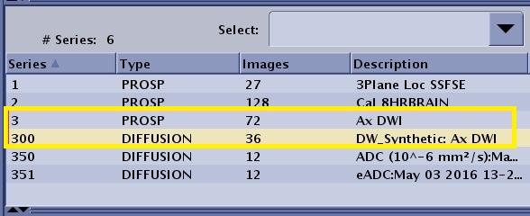 | ||||
| DynaPlan | N*100 + p
N*100 + K + p | N = original (base) series number, p=phase number
COL + PJN in separate series, where K= total #phases, p=phase number | ||||
| GSPS | N+100,000 | Add 100,000 to source series when creating GSPS objects | ||||
| FLEX IDEAL DISCO | N
100*N 100*N+1 100*N+2 (N*100)+99 N*100-1+i+k*nphase | N= original (base) series number which will always contain the Water images.
100*N: FAT 100*N+1: In-Phase 100*N+2: Out-of-Phase 100*N+99 only applies to IDEAL and not to Flex. The series is the 3 echoes of IDEAL that are collected during acquisition. IDEAL, unlike Flex, synthesizes in-phase and out-of-phase echoes since it does not collect these. Flex in-phase and out-of-phase images are true source images that are collected. 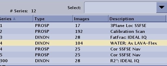 When multi-phase (dynaplan) is selected along with the separate series per phase option, the *100 series numbering changes as follows: Where i=phase number, k=0.3 (water, Fat, in-phase, out-phase, field map), note that the first water phase image is in series N which accounts for the –1. Again, there will be one block of numbers per image type with no place holders. Thus for N=4, 3 phases (0..2) W+F (0..1) the resulting series are: W(4 400 401) F(402, 403,404) 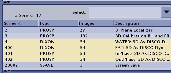 | ||||
| IDEAL IQ | N, Input series = N
100*N 100*N + 1 100*N + 2 100*N + 3 100*N + 4 | Triglyceride fat fraction images, series description: FatFrac: IDEAL IQ
R2* maps, series description: R2*: IDEAL IQ Water images, series description: Water: IDEAL IQ Triglyceride fat images, series description: Fat: IDEAL IQ In Phase, series description: InPhase: IDEAL IQ Out of Phase, series description: OutPhase: IDEAL IQ | ||||
| MAGiC | N*100+i N*100+i | N : original (base) MAGiC series number that contains MDME images. i : increasing number begins with 0 for all saved MAGiC images no matter if they are contrast weighted image series, Qmaps series, color qmap, screenshot.
| ||||
| Save Original | 40,000+N | N is the original series. Series description is prefaced with ORIG.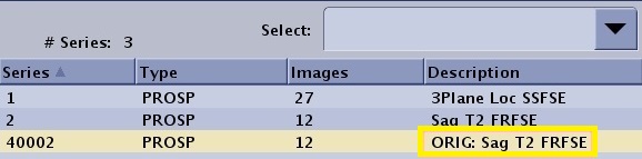 | ||||
| Phase Sensitive | N
N*100 | Series acquired with Phase Sensitive Imaging Option are stored in the Patient List as follows:
| ||||
| PROPELLER | N*100 (ADC),
N*100+1 (EADC), N*100+2 (CMB) | |||||
| Screen Save Auto | N+20,000 | Auto Screen Save from GRx screen saves | ||||
| Screen Save | 99 | |||||
| Text pages | 98 | All text page images are saved into series 98 with the following numbering scheme:
1..99 Exam text pages, page 1..99 as images 1..99 101..199 Series 1 text pages, page 1..99 as images 101..199 201..299 Series 2 text pages, page 1..99 as images 201..299 Thus for series N the text pages will be saved to images numbered: N*100+page_no | ||||
| T1Mapping | N*100 | The number of series generated is equal to the number of scan locations. For example, series 3 has 10 slice locations, the system does not create a series 3 in the patient list, but instead creates series 300-390 with each series being 10 phases of one scan location. 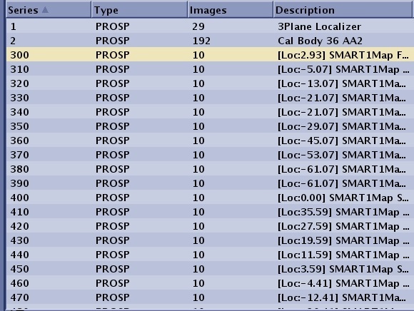 | ||||
| TRICKS | N (mask images)
N*100 (subtr collapse) N*100+i (temporal phase) N*100+50 (unsubtr collapse) N*100+50+i (unsubtracted) | i=1..n (temporal phases) | ||||
| VIBRANT | N*100+I | N = original (base) series containing all original images
I=0 pre-contrast image set, I=1..n post contrast subtracted images | ||||
| SWAN | 100*N
100*N+1 100*N+2 | N = original, the series number that always contains SWAN Magnitude images
100*N: SWAN Phase images 100*N+1: Reformatted SWAN Magnitude images 100*N+2: Reformatted SWAN Phase images 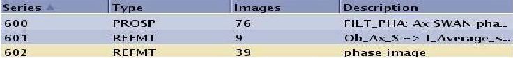 |