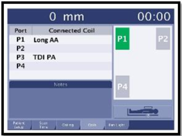
Indicates the port in which the coil is plugged into.
Connected Coil column:
Black text indicates the connected coil.
Orange text indicates that there is an operator action required.
Red text indicates that there is an error condition.
2
The Notes area displays coil messages or incompatibilities. Orange text indicates an operator action is required.
You can have multiple coils connected and only one of the coils requires an action, which will be indicated in orange.
You can have both coils in black text, and have an error. This scenario occurs when you have two coils plugged in that are incompatible.
3
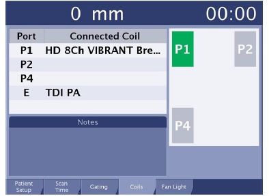
If Coil tab is orange consider the following:
There is an operator action required, which is posted in the Notes area.
You cannot proceed to scan until "Coil" in the tab is no longer orange.
Figure 2. Coil tab is not orange
The scan time is not displayed in the upper right corner of the display because you cannot proceed to scan when Coil is orange.
4
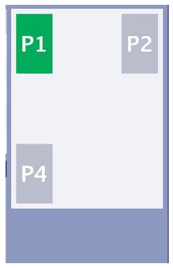
Coil port area is a representation of the coil connectors Figure 3. Coil port area is a representation of the coil connectors
Color scheme
Green ports indicate a coil is plugged in or active.
Orange ports indicate that an action must occur before the coil can become active.
Red and blue outlines indicate coil channels that are compatible with the port. View the Notes area on the coil tab for details.
Notes are displayed at the bottom of the screen to identify the problem.
Number system
P1 represents the left coil port located at the head end of the patient table. A green port that indicates it is active.
P2 represents the right coil port located at the head end of the patient table. An orange port that indicates an error state because the coil has not yet been defined.
P4 represent the coil ports located at the foot end of the patient table.