The following PROSE sequence allows you to acquire chemical shift images from a volume through the prostate gland as prescribed from valid localizer images of the prostate. This example prescription acquires spectra from isotropic CSI voxels that are 6.9 mm on each edge. Any changes in the suggested FOV (11 cm), phase encoding matrix selection (16x8x8), frequency direction (R/L), or spacing (6.9) may result in non-isotropic voxels, decreased SNR, or dramatic changes in scan time.
Step-by-step instructions
From the Workflow Manager, select the PROSE sequence and click Setup.
Select the coil name that only turns on the endo-rectal portion of the coil.
Review the scan parameters.
An axial oblique prescription that matches the tilt of the prostate gland, helps in the placement of the PROSE volume, such that it avoids the rectum and the endo-rectal coil.
The prominent resonance peak at ~2.6 PPM arises from the citrate molecules secreted by the prostate gland. Additional peaks that may be visible in the spectra at ~3.2 and ~3.0 are ascribed to the choline and creatine molecules, respectively. It is critical to suppress the water and fat signals; the Spatial Spectral RF Imaging Option is the optimal method for suppressing these signals. With Spatial Spectral RF, the water and lipid signals are not suppressed, but instead, water is partially excited, while the RF pulse does not excite the lipids. The SSRF excitation band is broad enough to tolerate a 25 Hz shift of the SSRF pulse and still excite the metabolites. In addition, the SSRF pulses have a strong non-linear, phase modulation that reduces peak RF power by 40%, an important consideration for body-coil excitation.
A TE value of 130 ms is recommended for best visualization of the citrate resonance peaks.
Click the Advanced tab and make adjustments as needed.
If the Scan Mode User CV = 1, select a typical TR of 1000 ms. A longer TR results in increased SNR at the expense of increased scan time. If the Scan Mode = 0, (voxel image) select the shortest allowed TR. For Scan Mode User CV details, see Scan Mode
An 11 cm FOV when used with 16 phase encoding steps along the frequency direction, yields a 6.9 mm CSI voxel edge.
A 16 Frequency and 8 Phase selections yield isotropic CSI voxels that are 6.9 mm on an edge. These settings provide good coverage of the prostate gland, good SNR, but a long scan time.
With an asymmetric CSI matrix selection (i.e., 16×8×8) the volume is FOV × FOV/2 x # CSI Slices x CSI Slice Thickness. The PROSE sequence sets an asymmetric CSI phase encoding volume so that the CSI voxels are cubes. The FOV divided by Freq/Phase determines the lengths of the in-plane edges of the CSI voxel. The length of the third edge is the CSI Slice Thickness value. For the suggested prescription, the edges are 6.9 mm (= 110/16 = 55/8 = CSI Slice Thickness).
Shim = Auto should always be selected to optimize the homogeneity through the voxel.
Graphically prescribe the PROSE ROI4 and the Voxel Thickness (VOI).
Select the axial or axial oblique T2 FSE series to prescribe the PROSE VOI.
Page through the images with the -/+ (Prior and Next) keys or the image slider to determine the location of the VOI
Click on the image to display the voxel.
CSI Slice Thickness of 6.9 should be the first default selection once the Frequency and Phase values have been selected in the Scan Parameters area. This value is calculated to produce an isotropic CSI volume. CSI Slice Thickness is the third dimension of the CSI voxels.
# CSI Slices is the number of phase encoding steps in the third dimension of the CSI phase encoding matrix.
The ROI should be sized and positioned so that the prostate gland is entirely within the ROI, while excluding the rectum and endo-rectal coil to minimize susceptibility artifacts.
Typical PROSE RL and AP dimensions are 55 mm and 35 mm, respectively.
If the Graphic Rx ROI is larger than the FOV value, an error message is posted and you cannot proceed to scan. Change the Graphic Rx ROI until the message is removed.
Do NOT prescribe the ROI from the SAT screen.
Set the Voxel Thickness to cover the prostate gland from its base to its apex, about 25 to 40 mm.
To define the first slice of the VOI, navigate to the desired slice, click the Graphic Rx toolbar and click Spectro > Start.
Scroll to the last slice you want covered by the VOI and click End to define the VOI thickness.
Note: Do NOT change the voxel thickness by any means after this step. If you need to change the VOI thickness, then click Erase All and start at step c.
Click Grid and only resize the VOI on the plane that displays the grid. If the CSI Grid displays in an orientation opposite the selected Freq DIR, then click on the VOI to re-orient the CSI Grid. Be certain to click on the VOI from the viewport that displays the CSI Grid
Place up to six SAT bands around the voxel to shape the volume or to suppress signals from lipid/fat within the voxel.
The VSSSAT bands can also be placed to reduce the effects of magnetic inhomogeneity near or around the voxel.
Thirty-six VSS RF suppression pulses are available. Six sets of three repeated VSS pulses (18 in all) define the PROSE volume – the localized volume is expanded by 10 to 30%. The remaining eighteen (in six sets of three repeated pulses) can be graphically placed to shape, and/or to suppress lipid signals in tissue at the corners or edges of the PROSE volume.
Click SaveRx.
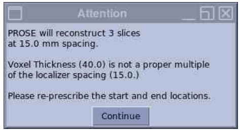
An Attention message displays informing you of the slices that will reconstruct and the spacing which is the thickness + spacing of the localizer image.
Figure 1. Attention message
It may also display a message regarding the VOI Thickness. This message displays if the VOI Thickness is not a multiple of Localizer thickness + spacing. This can easily occur if you change the shape of the VOI on one of the viewports that does NOT display the CSI Grid. If you get this VOI Thickness mismatch, then select the VOI, click Erase Selected and re-prescribe the VOI. Click Continue on the Message box.