- 00000018WIA3005B970GYZ
- id_400248151.4
- Mar 29, 2022 1:06:12 PM
Reformat workflow
Before you begin
Reformatting allows you to define and display cross-sections of a 2D stack or 3D volume of image data that are oriented differently from the original acquisition images.
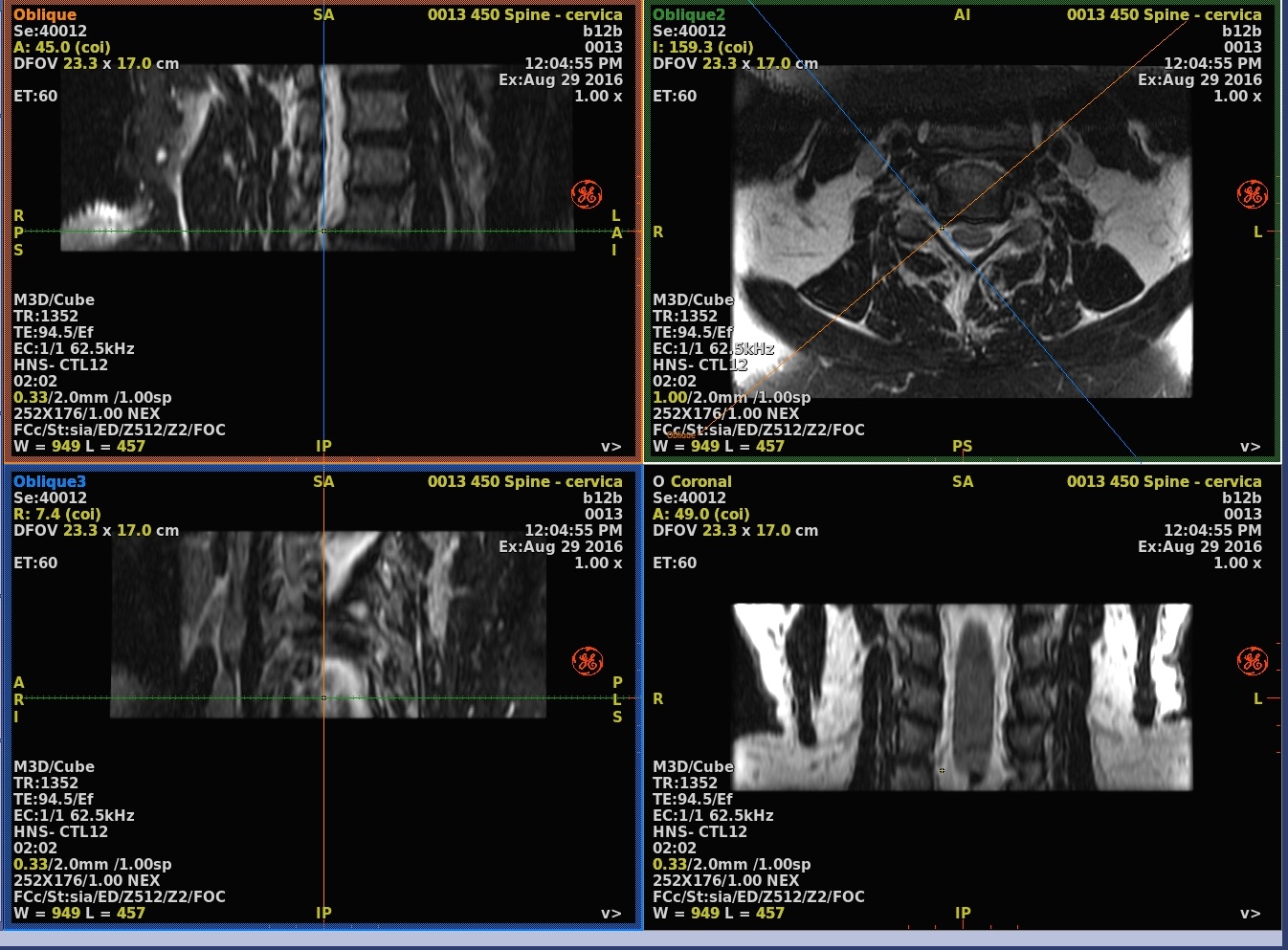
A baseline view is a basic axial, coronal or sagittal view. Of these, the acquisition view displays the images in the acquisition plane of the original image set, the other two are the corresponding orthogonal reformatted views. They can be moved to show any location in the 3D volume, but remain aligned parallel to the three main axes of the RAS coordinate system. An oblique view is a plane reformatted view that can be both moved and rotated to any location and orientation within the 3D volume.
If a feature of interest extends beyond a single plane, standard baseline or oblique view reformatting cannot show the entire feature no matter how you position the oblique plane. To create a single view that includes the entire feature, use curved reformatting to create a curved cross-section.
Reformat is primarily used for MRA, MRCP, and IAC applications.
About this task
Step-by-step instructions
- Adjust the render mode from Average to MIP.
Figure 1. Render mode annotation 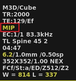
- Click the axial viewport to make it active, and from the Visualization toolbar, click the Simple Oblique icon (
 ) and a solid line cursor in the center of two dotted line cursors appears representing the thickness of the plane displayed in the Oblique viewport.
 - Click on the Oblique icon (
 ) to create a double oblique, if applicable.
- Optional: Click the Measure/Annotate toolbar to add measurements or annotation.
- Optional: Save an individual image.
Figure 2. Reformat viewports