- 00000018WIA30520870GYZ
- id_400265981.5
- Nov 10, 2021 4:51:37 PM
The B0 field
When we speak of an MRI magnet “field” we usually mean the main magnetic field, or B0 field. In this topic, a 1.5T magnet is used to illustrate B0 concepts.The center of a 1.5T magnet has a B0 field of 1.5 Tesla, or 15,000 Gauss. The B0 field decreases rapidly as you move away from the bore; at 2 meters from isocenter, this field is down to several percent of the field at isocenter.
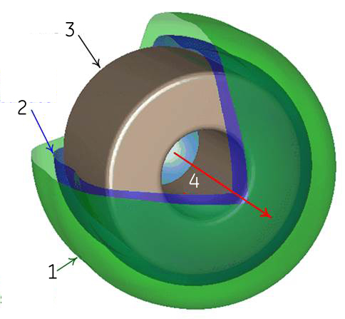
The shape of the B0 field approximately matches that of the magnet and (typically) the enclosures encapsulating it. The cylindrical magnets used in MRI create a roughly barrel shaped field outside the magnet. Figure 1 shows two isocontours (surfaces of constant magnetic field strength) for a typical 1.5T magnet’s B0 field. The green surface shows where the field strength is 300 G, which is 2% of the field at center. The blue surface is 1200 G, or 8%. (One quadrant is removed for clarity.)
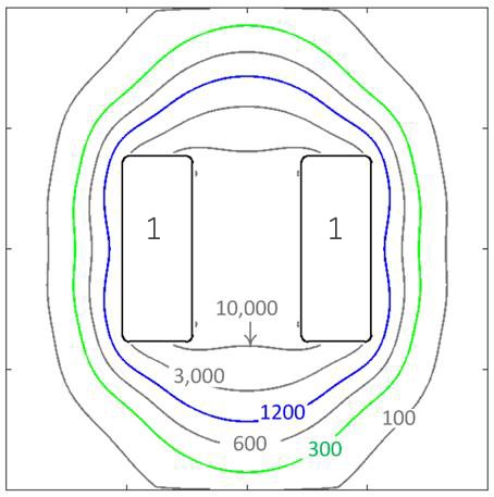
A contour map, or contour plot, is a two dimensional diagram of a slice through this 3D field. Figure 2 shows the same field as Figure 1 – translated into a contour map. The map shows the field contours on a horizontal plane through the center of the magnet. The 300 and 1200 G contours are shown along with several others (100, 600, 3000, and 10000 G). You can see how the contour shapes match between the two figures.
It is important to understand and remember that the magnet’s field is in three dimensions, shaped roughly like the magnet, and that the contour maps commonly used are two dimensional representations of the actual field.
| Number | Description |
|---|---|
| 1 | 300 G surface |
| 2 | 1200 G surface |
| 3 | Magnet |
| 4 | B0 field |