

- 00000018WIA30D20870GYZ
- id_400269321.3
- Nov 23, 2021 11:33:00 AM
Field strength and bore comparisons
For an example of 1.5T spatial gradient see Figure 1.
For an example of 3.0T spatial gradient see Figure 2.
Since the main magnetic field doubles between 1.5T and 3.0T, the spatial gradient of the field will approximately double, given similar magnet designs.
Therefore, the SG exposure approximately doubles for 3.0T compared to 1.5T, for similar locations within the bore.
60 versus 70 cm
Since the magnet designs are similar for 60 cm and 70 cm scanners, the spatial gradient is similar at most locations, relative to the center of the magnet. However, a 70 cm system has a larger bore, and can reach higher SG contours. Therefore, the SG near the bore walls of a 70 cm system are higher than those for a 60 cm system.
This difference is approximately 20%.
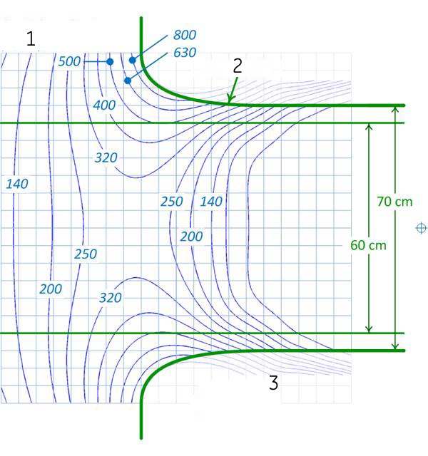
| Number | Description |
|---|---|
| 1 | Spatial gradient (G/cm) (blue lines) |
| 2 | Bore wall (bold green lines) |
| 3 | Area inside enclosures |
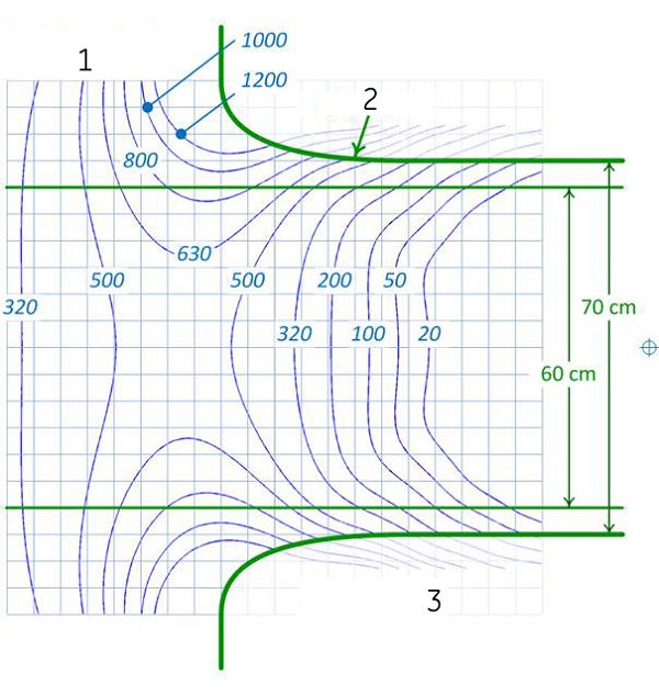
| Number | Description |
|---|---|
| 1 | Spatial gradient (G/cm) (blue lines) |
| 2 | Bore wall (bold green lines) |
| 3 | Area inside enclosures |