

- 00000018WIA30B20870GYZ
- id_400214831.6
- Mar 1, 2022 12:49:29 AM
Locations of spatial gradient occurrences
A clear understanding of the spatial gradient inside the bore is useful. In general, spatial gradients “reach into the bore” near the mouth of the magnet. A higher SG reaches less into the bore than a lower one. Figure 1 (again a typical 1.5T magnet) gives some insight. In this example, two spatial gradient contours are compared: 320 and 400 G/cm. The 320 contours reach into the bore far enough to leave a 28 cm gap. The 400 G/cm contours leave a 48 cm gap.
Given the three dimensional shape of the field, these gaps translates into a circular opening, centered on the magnet’s z axis; when extended along the z-axis, this circle becomes a cylinder, centered in the bore. Staying within this cylinder assures that you stay away from a high spatial gradient. In this example, staying within a 28 cm diameter cylinder keeps the spatial gradient below 320 G/cm.
Rather than trying to visualize a cylinder, it may be easier to think of staying a certain distance away from the bore wall. Example: for a 70 cm system and a 48 cm gap, this distance is 11 cm, as shown below.
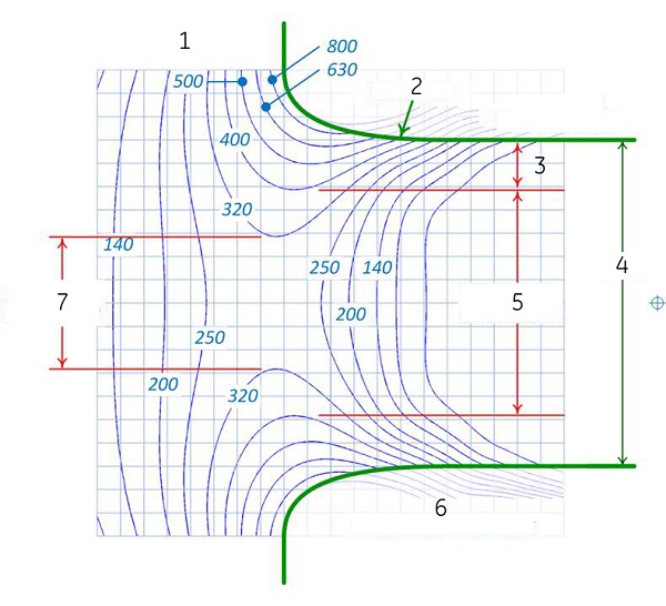
| Number | Description |
|---|---|
| 1 | Spatial gradient (G/cm) (blue lines) |
| 2 | Bore wall (green lines) |
| 3 | 11 cm from 70 cm bore wall |
| 4 | 70 cm bore diameter |
| 5 | 48 cm gap at 400 G/cm |
| 6 | Area inside enclosures |
| 7 | 28 cm gap at 320 G/cm |
Thresholds
There is a lower SG threshold, below which there is no path into the center of the magnet. In this example, there is no path into the magnet that does not pass thru the 250 G/cm contours. We can call this threshold the “entry SG.”
There is also an upper threshold where the allowable cylinder is the same size as the bore. In this example, the 800 G/cm contour has at least a 70 cm gap. The tapers near the ends of the bore still require care.
Summary
- There is a lower SG threshold, below which there is no path to get to the center of the magnet.
- There is an upper SG threshold, above which the bore diameter limits the SG exposure.
- Between these thresholds, SG values can be limited by staying within a cylinder, whose diameter increases as the SG values increases.
Outside the bore
- All areas outside the box should have lower SG exposure than the lower SG threshold or “entry SG” described on the previous slide.
- The distance should be something easy to visualize and remember.
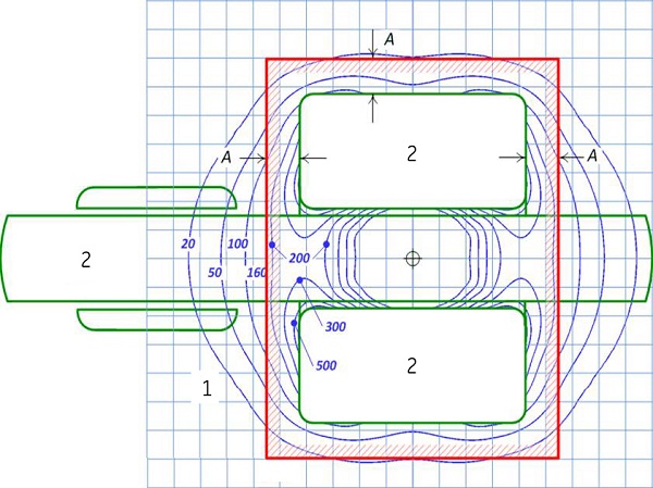
| Number | Description |
|---|---|
| 1 | Spatial gradient (G/cm) (blue lines) |
| 2 | Patient table and magnet (green lines) |
In this example, the box is sized so that it encloses all the spatial gradient regions above 200 G/cm. This uses a distance of 25 cm (almost exactly 10 inches) from the enclosures.
Everywhere outside of the box, the SG is less than 200 G/cm, which in turn is less than the entry SG threshold at the mouth of the magnet. Therefore, the limiting case for SG exposure will always be at the mouth of the magnet, as opposed to the box around the magnet and enclosures.
Controlling spatial gradient exposure
The ideas covered in the previous examples can be combined to give a more complete picture of how to control spatial gradient exposure.
Figure 3 shows the concept of the box around the magnet, combined with the cylinder inside the bore. The right sketch is a two dimensional diagram, looking down from above, on the plane at the center of the magnet.
The size of the box, given by distance A in Figure 4, does not change with the SG level. All areas outside the box have low spatial gradient compared to the entry SG. The size of the cylinder does change with SG level. The cylinder diameter increases as SG level increases – or put another way, the distance between the cylinder and the bore wall, which is distance D in Figure 4, decreases with increasing SG level.
For a specific magnet or system, setting distances A and D define the areas that need to be avoided to keep spatial gradient exposure below any specific level.
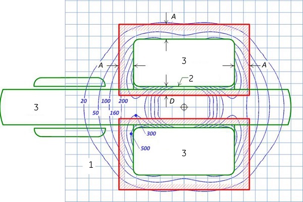
| Number | Description |
|---|---|
| 1 | Spatial gradient, G/cm (blue lines |
| 2 | Bore wall |
| 3 | Patient table and magnet (green lines) |