- 00000018WIA300C3870GYZ
- id_400264071.16
- Jul 5, 2022 11:02:51 PM
RF coils
Imaging coils are tuned to match the precessional frequency of nuclei under evaluation. Generally, the length of coil is equal to the FOV the coil covers. The depth of penetration is governed by the coil elements. When selecting a coil, keep in mind the FOV, how deep you need to image, and the size of the patient. Phased array and surface coils need to be placed close to the area of interest. The broad category of imaging coils can be classified into two categories:
- transmit and receive coils
- receive only coils
 Each coil, other than the body coil, has an operator manual. Refer to the coil operator manual when setting up the patient for an exam.
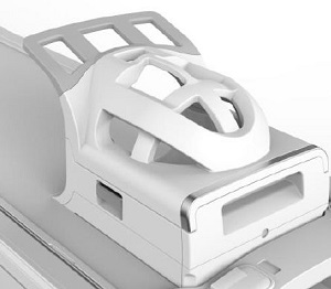
Head coil
The TDI Head Neck Array is a receive only coil.
The head coil provides higher SNR (Signal-to-noise ratio) than the Body coil due to the smaller size. It is used primarily to image the head, although they can be used for imaging any body part that fits into the coil. It is an example of a volume (uniform depth of signal) coil.
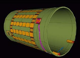
Body coil
The Body coil is a transmit/receive volume coil used for large FOV imaging and for uniform depth penetration. The Body coil is located within the magnet enclosure and is invisible to you and the patient. The Body coil can also act as a transmit only coil when used with receive only coils.
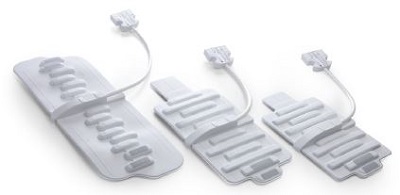
Surface coil
Surface coils are receive only coils that can be either single or multiple channels. Phased array (multi-channel) coils have a number of coil elements combined together to increase SNR, and depending on the coil design, may increase available FOV (either length or depth) without decreasing SNR. Flat surface and phased array coils do not have uniform depth penetration.
The transmit mode of the coil appears on a label adhered to the coil. A T/R label refers to a transmit/receive coil.
There are some coils commonly referred to as surface coils, such as the Knee coil, that are in fact transmit/receive coils. Therefore, technically, they are not a surface coil.
Multi-channel surface coils can help you improve productivity, a crucial consideration in today’s competitive scanning environments. These devices can be optimized for parallel imaging techniques, improved SNR, and can provide better image resolution. Parallel imaging techniques, like ASSET or ARC, reduce scan times, which can decrease patient exam times. Reduced coil diameter together with multi-channel phased array elements over a given volume increase SNR and thereby resolution.
Coil positioning tips
- Choose the coil most appropriate for the corresponding anatomy of interest and required FOV.
- Landmark on the coil marker, not on the patient’s anatomy. The landmark line(s) on the coil indicate the center of the coil for each coil configuration. Imaging coils will function most accurately when placed at the magnet’s isocenter.
- If the coil has multiple configurations, select the appropriate number of elements according to the area that needs to be covered.
- If the coil has multiple configurations, center the coil elements corresponding to the coil configuration chosen over the region of interest.
- All coils have a coil ID. There are two purposes for Coil ID: matching the coil plugged in with the selected coil in the prescription, and checking if the coil is properly seated in the port.
- To connect coils to your MR system, see Connect coils.
Coil malfunction considerations
Coil decoupling mechanisms are circuits activated by diodes to prevent RF currents from flowing in the receive-only coil during transmission from the Body coil. This results in local distortion of the transmit field and signal intensity variations within the image.
If you suspect a coil malfunction, consult your service engineer and discontinue use of the coil.
Coil signal non-uniformity considerations
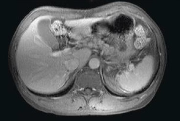
The RF receiver detects signals closest to it most efficiently. This characteristic may cause a non-uniformity of signal in the image. The effect is more pronounced with surface coils than with volume coils, appearing as localized bright areas close to the coil. Signal variability may also result in incomplete fat suppression when chemical fat suppression techniques are used.
To minimize the chance of non-uniformity of signal in a coil:
- try a different coil or use a STIR sequence rather than trying additional fat saturation techniques
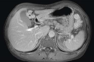
- apply a coil intensity correction option
- the availability of various intensity correction options depends on your system configuration and compatible surface coils
- apply a coil intensity correction technique, such as PURE.
- PURE can be used with the 8-channel transmit/receive high resolution MRI Devices Knee coil