

- 00000018WIA30580880GYZ
- id_20342511.28
- Jul 5, 2022 11:33:46 PM
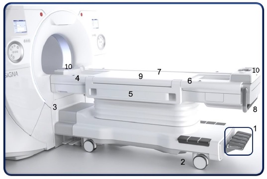
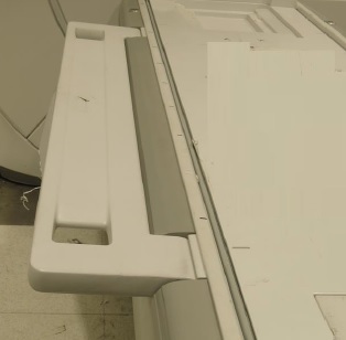
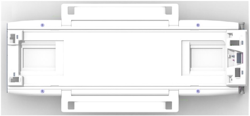
Detachable table
The detachable patient table is a patient transport device that can be removed from the scan room to simplify positioning patients and to speed scan room evacuation in emergency situations.
| Number | Description |
|---|---|
| 1 | Table pedals |
| 2 | Brake/Steer-lock caster |
| 3 | Table base controls |
| 4 | IntelliTouch |
| 5 | Side rails/arm boards |
| 6 | IV pole |
| 7 | Patient security straps (not shown) |
| 8 | Table transport handle |
| 9 | Embedded posterior array coil. Filters are located at the north and south end of the table top |
| 10 | Coil ports |
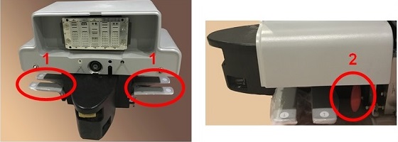
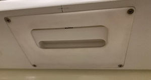
Table pedals and emergency release lever


There are also up and down pedals located on either side of the magnet base and an emergency release lever. The electronic or manual dock connection is located at the magnet end of the table. For table emergency release details, see Mobile table emergency release.
| Number | Description |
|---|---|
| 1 | Up/down pedals |
| 2 | Transport/emergency release lever |
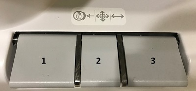
Brake/steer/lock caster
There are three casters/pedals: brake, steer and lock.
IntelliTouch
The IntelliTouch landmark strip is located on either side of the table.
Side rails/arm boards
Raise the side rails when using the table to move patients between locations.
The side rails or arm boards are located on either side of the table. The rails in the horizontal locked arm board position will support 60 pounds.
The arm boards can be moved to a down position and hold any position between the horizontal (90 degree) position and the top most (150 degree) position from vertical
To unlock the arm board from its current position, squeeze the lever underneath the arm board.
IV pole
The MR compatible IV Pole can be inserted into the receiver holes located on either side of the table and at the foot and head end of the table.
Patient security straps
The security straps can be slid into both sides of the table from either the head or foot end. Security straps across the arms, abdomen, or legs provides safety for the patient and help control patient motion.
Cradle release handle
To remove the cradle from the magnet bore, see Cradle emergency release and re-engagement.
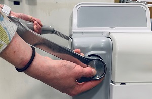
Table transport bar
The table transport bar can be raised to a comfortable position so that you can move the table. To move the bar into the up position, press the silver button on the side of the table.
To avoid pinching fingers or hands between the table and other objects, place your hands on the top of the table transport bar when moving the table.
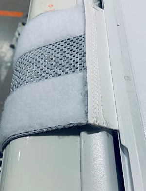
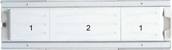
Embedded posterior array coil
The table is divided into thirds: the coil array and the magnet and foot end. The fillers provide a flat surface on which the patient is positioned. The fillers can be removed and replaced with a compatible coil, for example the head or neurovascular array coil, or stay in place and be used with coils such as a flex coil or the anterior array coil.
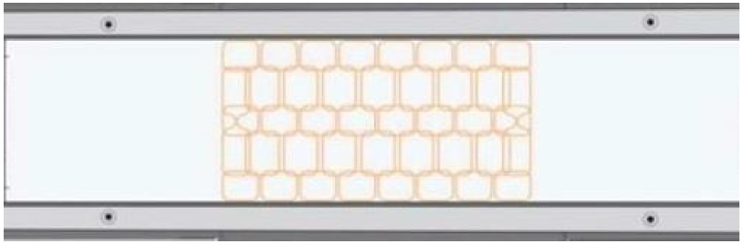
TDI posterior array
The TDI posterior array has 32 elements. Both are 120.5 cm long and 48.6 cm wide, and are designed to support parallel imaging in all 3 planes.
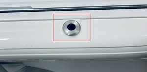
Coil ports
To connect coils to your MR system, see Connect coils.
Microphone and speaker
There are two microphone/speakers located on both ends of the table.
PAC ports
There are four Physiological Acquisition Control ports:
- patient alert device
- respiratory bellow
- peripheral gating device
- ECG device
For patient alert details, see Patient alert.
For PAC details, see PAC-in-table connections.