

- 00000018WIA30CF2C80GYZ
- id_20363071.1
- Feb 1, 2022 6:22:47 PM
ECG patient setup
Before you begin
- Abrasive gel, such as NuPrep
- Cotton swabs or gauze pads
- MR-approved electrodes, such as:
- E8819RB MRI Quadtrode Electrodes
- E8819RF Vermed Medical 1004-5 Series ECG Electrodes
- E8819RG ConMed Cleartrace ECG
Note: Check the expiration date of each electrode before use. Do not use expired electrodes. - ECG lead connector
- Respiratory bellows connector
- Square pad, to use between patient and cardiac leads
About this task
For more information, see Set up the ECG gated exam.
Step-by-step instructions
- Position the ECG leads.
- Place and secure the respiratory bellow.
- If desired, attach the peripheral gating line.
- From the operator console, in the Footer area, click the Gating, Fan, Light icon (
 ).
).Result
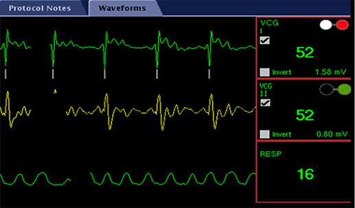
The Gating Control screen appears. - On the Gating Control screen, select Cardiac Gating in the Waveform Display area.
- Select Standard Gating Mode below Cardiac Gating Selection.Note: In Standard Gating mode, you can only show one ECG waveform at a time. Use the radio buttons to select the desired waveform.
- Place electrode (1) superior to the apex of the heart.
- Place electrode (3) inferior to (1) to create VCGI, as demonstrated by vector (5).
- Place electrode (2) and (4) orthogonal to VCGI to create VCGII, as demonstrated by vector (6).
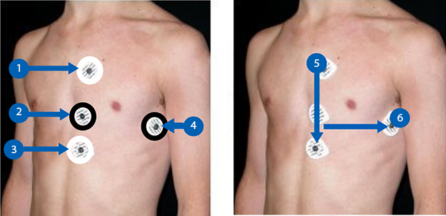
- Use the white cardiac lead pair with the white and red clips attached to the electrodes (1) and (3) to create VCGI.
- Use the black cardiac lead pair with the green and black clips attached to electrodes (2) and (4) to create VCGII.
 Note:
Note:- The leads should have slack. If they are pulled too tightly, the ECG trace may become compromised.
- You can connect the white and black lead pair in any direction if the pairs remain orthogonal.
Warning