

- 00000018WIA30852870GYZ
- id_400249701.22
- Jul 26, 2022 12:06:06 PM
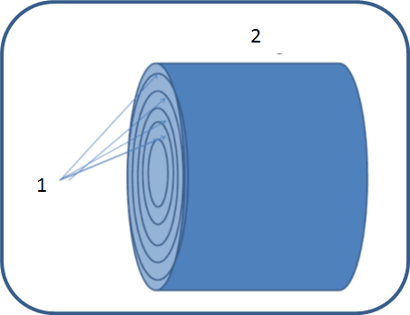
Static spatial gradients on concentric cylinders
The static magnetic field might cause forces or torques on some devices near the magnet. The following table shows the maximum magnetic field (B0), the spatial rate of change of the magnetic field (grad(B0)), and the product of the magnetic fields and its rate of change (B0*grad(B0)) for infinitely long cylinders concentric with the patient bore. This information may be of use in evaluating risk assuming patients are confined to the cylinder bounds. Note that higher values of these parameters exist on the magnet bore covers (see above).
For example, for the SIGNA Voyager system LCCW magnet, use below table to find the peak static gradient field in the 70 cm bore is 6.4 Tesla/m. The peak spatial gradient in the patient bore is located on the 70 cm cylinder surface at z = 0.735 m from isocenter. The user then evaluates the risk from the device manufacturer’s MR Conditional Labeling, from the characteristics of the scanner, and from other information such as patient history.
- First find that the maximum peak gradient on the magnet covers (from the above table) is 6.4 Tesla/m (640 gauss/cm). This peak occurs at a radius of 0.35 m of axis and a z location 0.74 m from isocenter (typically on the magnet covers). Some risk managers consider this information adequate for determining risk from static spatial gradients.
- Some risk managers may limit the patient to regions contained by cylinders concentric with the patient bore. They may use the table below to find that the maximum spatial gradient in the bore is 6.4 Tesla/m (640 Gauss/cm). The peak spatial gradient in the patient bore is located on the 70 cm cylinder surface at z = 0.74 m from isocenter. The user then evaluates the risk from the device manufacturer’s MR Conditional Labeling, from the characteristics of the scanner, and from other information such as patient history. In this case the peak static gradient is same as the maximum value on the magnet cover.
For example, for the SIGNA Voyager system IPM magnet, use below table to find the peak static gradient field in the 70 cm bore is 5.7 Tesla/m. The peak spatial gradient in the patient bore is located on the 70 cm cylinder surface at z = 0.784 m from isocenter. The user then evaluates the risk from the device manufacturer’s MR Conditional Labeling, from the characteristics of the scanner, and from other information such as patient history.
- First find that the maximum peak gradient on the magnet covers (from the above table) is 5.7 Tesla/m (570 gauss/cm). This peak occurs at a radius of 0.350 m of axis and a z location 0.78 m from isocenter (typically on the magnet covers). Some risk managers consider this information adequate for determining risk from static spatial gradients.
- Some risk managers may limit the patient to regions contained by cylinders concentric with the patient bore. They may use the table below to find that the maximum spatial gradient in the bore is 5.7 Tesla/m (570 Gauss/cm). The peak spatial gradient in the patient bore is located on the 70 cm cylinder surface at z = 0.78 m from isocenter. The user then evaluates the risk from the device manufacturer’s MR Conditional Labeling, from the characteristics of the scanner, and from other information such as patient history. In this case the peak static gradient is same as the maximum value on the magnet cover.
| Number | Description |
|---|---|
| 1 | Concentric cylinders |
| 2 | Magnet |
To determine your system configuration (magnet and gradient type) view the About MR scanner. To access About MR Scanner, seeAbout MR Scanner .
1.5T LCCW magnet
| Field magnet | Item | On patient Z axis | On 20 cm Diameter Cylinder surface | On 30cm Diameter Cylinder surface | On 40cm Diameter Cylinder surface | ||||
|---|---|---|---|---|---|---|---|---|---|
| Peak | R,Z (m,) | Peak | R,Z (m,m) | Peak | R,Z (m,m) | Peak | R,Z (m,m) | ||
| 1.5T LCCW | Bo (T) | 1.5 | (0,0.23) | 1.5 | (0.1,0.374) | 1.5 | (0.15,0.465) | 1.5 | (0.2,0.525) |
| Gradient (T/m) | 2.7 | (0,0.84) | 2.8 | (0.1,0.836) | 3.0 | (0.15,0.81) | 3.3 | (0.2,0.805) | |
| BxG (T2/m) | 2.8 | (0,0.77) | 3 | (0.1,0.763) | 3.3 | (0.15, 0.775) | 3.8 | (0.2,0.745) | |
| Field Magnet | Item | On patient Z axis | On 50cm Diameter Cylinder surface | On 55 cm Diameter Cylinder surface | On 60cm Diameter Cylinder surface | On 70cm Diameter Cylinder surface | |||||
|---|---|---|---|---|---|---|---|---|---|---|---|
| Peak | R,Z (m,m) | Peak | R,Z (m,m) | Peak | R,Z (m,m) | Peak | R,Z (m,m) | Peak | R,Z (m,m) | ||
| 1.5T LCCW | Bo (T) | 1.5 | (0,0.23) | 1.6 | (0.25,0.57) | 1.6 | (0.275,0.59) | 1.7 | (0.3,0.6) | 2.0 | (0.35,0.62) |
| Gradient (T/m) | 2.7 | (0,0.84) | 3.7 | (0.25,0.83) | 4.1 | (0.275,0.79) | 4.6 | (0.3,0.75) | 6.4 | (0.35,0.735) | |
| BxG (T2/m) | 2.8 | (0,0.77) | 4.7 | (0.25,0.75) | 5.5 | (0.275,0.74) | 6.5 | (0.3,0.72) | 11.0 | (0.35,0.69) | |
1.5T IPM magnet
| Field magnet | Item | On patient Z axis | On 20 cm Diameter Cylinder surface | On 30cm Diameter Cylinder surface | On 40cm Diameter Cylinder surface | ||||
|---|---|---|---|---|---|---|---|---|---|
| Peak | R,Z (m,) | Peak | R,Z (m,m) | Peak | R,Z (m,m) | Peak | R,Z (m,m) | ||
| 1.5T IPM | Bo (T) | 1.5 | (0.000,0.000) | 1.5 | (0.100,0.000) | 1.5 | (0.150,0.000) | 1.5 | (0.200,0.000) |
| Gradient (T/m) | 2.6 | (0.000,0.862) | 2.8 | (0.100,0.868) | 3.0 | (0.150,0.829) | 3.2 | (0.200,0.823) | |
| BxG (T2/m) | 2.7 | (0.000,0.777) | 2.9 | (0.100,0.780) | 3.3 | (0.150,0.737) | 3.7 | (0.200,0.774) | |
| Field Magnet | Item | On patient Z axis | On 50cm Diameter Cylinder surface | On 55 cm Diameter Cylinder surface | On 60cm Diameter Cylinder surface | On 70cm Diameter Cylinder surface | |||||
|---|---|---|---|---|---|---|---|---|---|---|---|
| Peak | R,Z (m,m) | Peak | R,Z (m,m) | Peak | R,Z (m,m) | Peak | R,Z (m,m) | Peak | R,Z (m,m) | ||
| 1.5T IPM | Bo (T) | 1.5 | (0.000,0.000) | 1.6 | (0.250,0.573) | 1.6 | (0.275,0.584) | 1.6 | (0.300,0.604) | 1.8 | (0.350,0.624) |
| Gradient (T/m) | 2.6 | (0.000,0.862) | 3.7 | (0.250,0.835) | 4.1 | (0.275,0.781) | 4.5 | (0.300,0.813) | 5.7 | (0.350,0.784) | |
| BxG (T2/m) | 2.7 | (0.000,0.777) | 4.5 | (0.250,0.740) | 5.5 | (0.275,0.738) | 5.9 | (0.300,0.765) | 8.5 | (0.350,0.736) | |