- 00000018WIA30FFDC80GYZ
- id_20365881.5
- Jun 14, 2022 12:24:24 AM
Artifacts
This quick reference guide explains typical artifact appearances and how to mitigate them.
| Artifact | Image | Cause | Recommendation |
|---|---|---|---|
| Annefact Ribbons of signal | 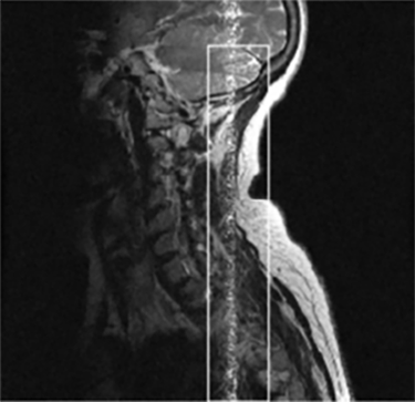 | Signal generated outside of the FOV |
|
| ASSET Aliasing Anatomy aliases back into center of image | 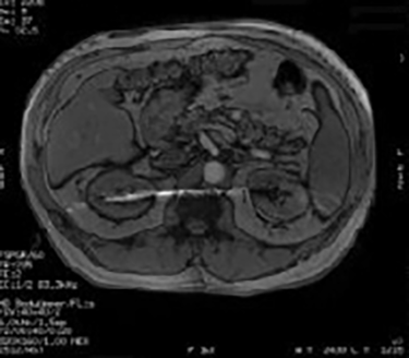 | Breathing or motion between calibration scan and accelerated scan |
|
| Blurring or Ghosting Smearing in image | 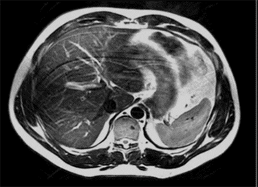 | Blurring and ghosting can be caused by patient motion, cardiac motion, or respiratory motion. |
|
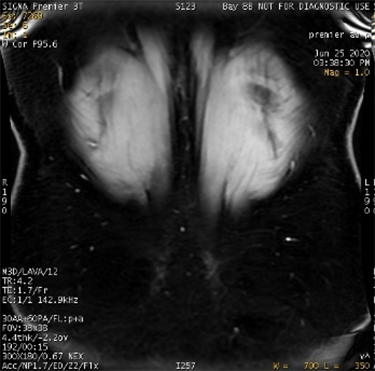
| Bulk Susceptibility (C-spine Fat Sat Uniformity) Poor chemical fat sat uniformity | 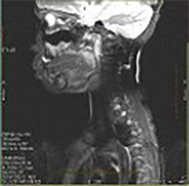 | Poor B0 uniformity |
|
| Calibration Mis-registration Mottled appearance in anatomy | 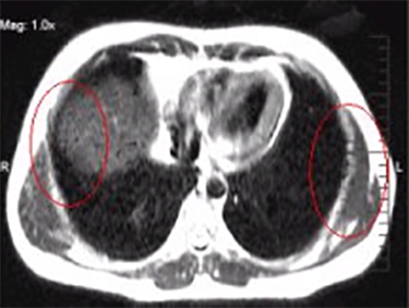 | Mismatch of patient anatomy between calibration scan and accelerated scan | Repeat the calibration scan. |
| Chemical Shift Boundaries between fat and water are either bright or dark | 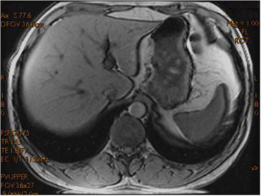 | TE timing is incorrect | The system should auto select the appropriate TE values:
|
| Dielectric Effect Inhomogeneity/Shading in the image | 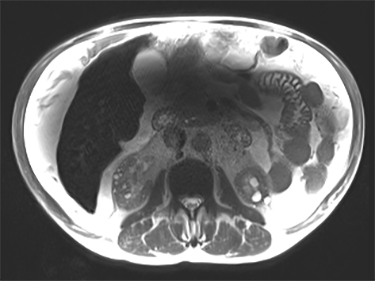 | Interaction of matter with electrical component of RF field |
|
| DWI/DTI Ring Ring-like artifact | 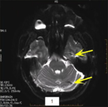 | Intense orbit signal |
|
| Fat/Water Swap Areas that should appear fat suppressed are water suppressed, and ar-eas that should appear water suppressed are fat suppressed | 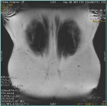
| Decreased linearity at the corners of the FOV corrupt the signal. The fat water identification algorithm may become confused, which results in a full series fat/water image swap. Phase wrap in slice and phase direction also influence swaps. This error may occur in regions of high magnetic field variation, in spatially isolated tissue, and/or in images with low signal-to-noise ratios, due to:
|
|
| Fine Line Artifact Appears as small, wavy lines throughout the image | 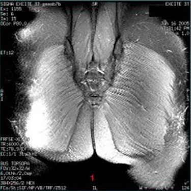 | Unsuppressed FID signals, often from using odd NEX |
|
| Metal/Susceptibility Signal void, image distortion | 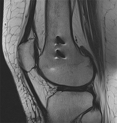 | Occurs when a metal implant is present |
|
| Non-Uniformity Bright areas closer to the surface of patient’s body where the coil is | 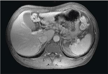 | The RE receiver detects the signal that is closest to the coil. |
|
| PROPELLER- Crinkling Slight signal voids, most commonly in superior slices | 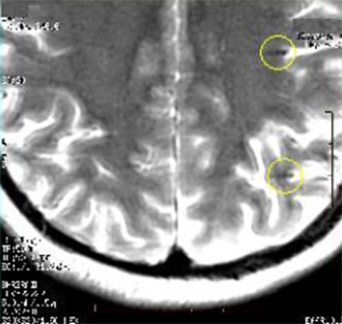 | Incorrect ETL, extreme patient motion, or phase wrap |
|
| PROPELLER - Top of Scalp Artifacts Noise in image background | 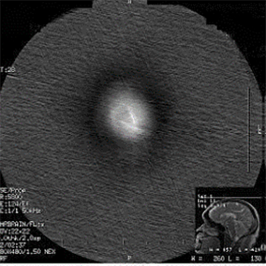 | Slices positioned too far superiorly | Prescribe fewer slices to cover only anatomy of interest. |
| PROPELLER - Blurring Blurred images | 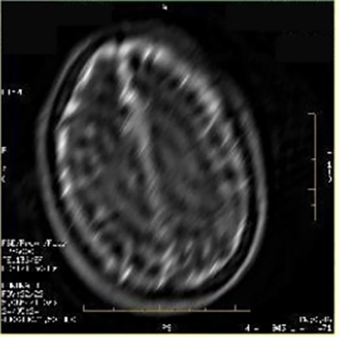 | Mismatch of PROPELLER blades | Updates to PROPELLER should avoid blurring due to mismatch of blades. If blurring occurs, re-prescribe the series and scan again. |
| PROPELLER - Signal Voids Black holes in DWI PROPELLER images | 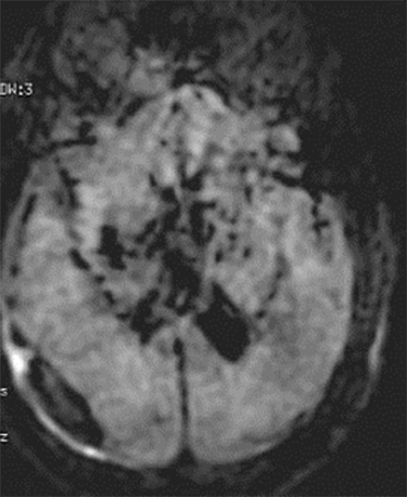 | System calibrations out of specification | Contact service to ensure that the system is within specification. |
| PROPELLER - Ripples Rippling in images | 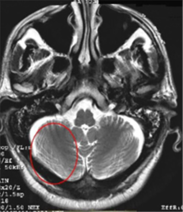 | Phase wrap in a radial acquisition |
|
| PROPELLER - RF Leak Zipper artifact criss-crossing in image | 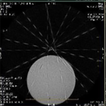 | RF leak in a radial acquisition appears across the entire image | Ensure that there are no RF leaks in the room due to an open door, faulty light bulb, etc. |
| PROPELLER - Streaking Noise in image appearing as streaks, most prevalent in the background | 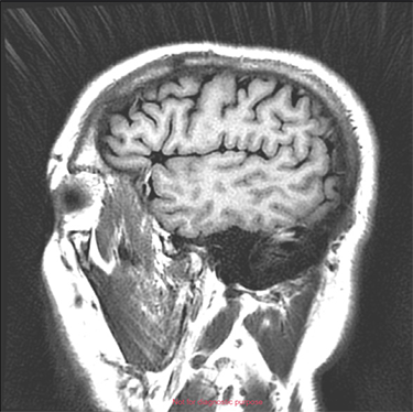 | Oversampling in a radial acquisition that aliases back into the image |
|
| RF Inhomogeneity Intensity variations across an image | 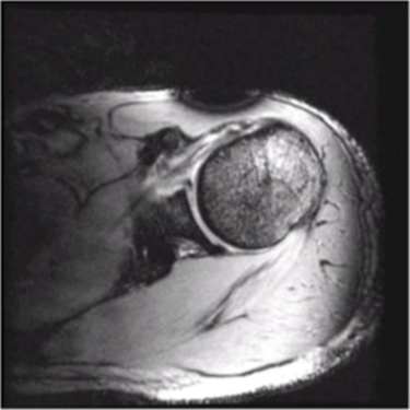 | This often indicates the failure of a coil element or the presence of ferromagnetic material. |
|
| RF Leak Corduroy effect across image, or one solid line through image | 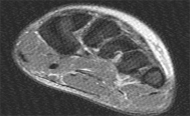 | RF leak in the room | Ensure that there are no RF leaks in the room due to an open door, faulty light bulb, etc. |
| B0 Inhomogeneity Area of reduced signal intensity or bands of signal cancellation | 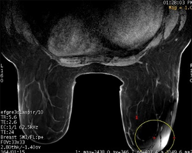 | Improper coil or patient position |
|
| B1 Shading Appears as reduced signal intensity | 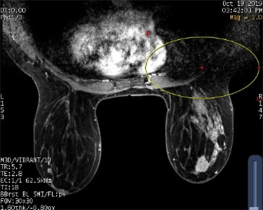 | Spatial inhomogeneity in the B1 field. RF does not distribute evenly across the body, so some areas appear darker. |
|
| Silenz Streaking Slight streak artifact through portions of the image | 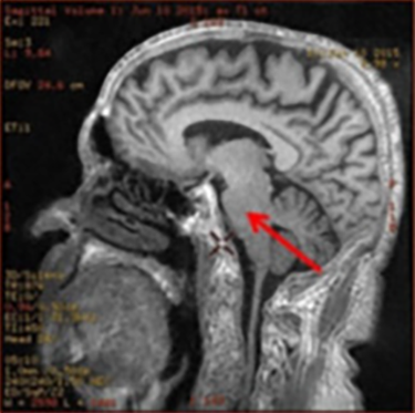 | Signal outside of the FOV |
|
| Star Bright spot close to the center of the image | 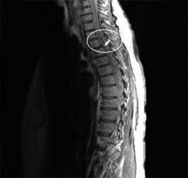 | Signals generated outside the desired FOV that are detected by the receiver |
|
| Ringing (Truncation, Gibbs) Appears around bright tissue, enhanced if the brightness changes sharply | 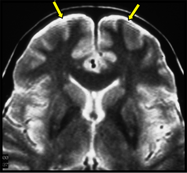 | K-space data is not completely acquired |
|
| Wormholes Signal voids in a DWI or EPI image | 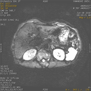 | Larger shifts in K-space data due to motion within the diffusion lobe |
|
| Wrap (Aliasing) Image fold onto the opposing side of anatomy | 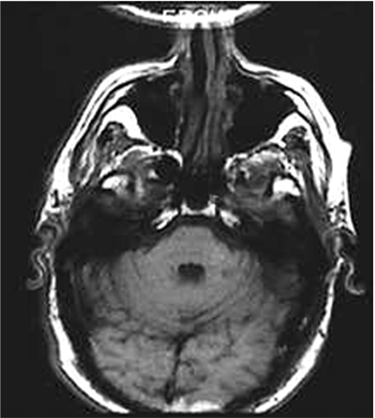 | Wrap is caused by the collection of data in the K-space wrapping into anatomy due to insufficient coverage of the FOV. |
|