- 00000018WIA30932870GYZ
- id_400238221.36
- Aug 29, 2022 2:11:49 PM
Peak static spatial gradients on patient accessible areas table
See Peak static spatial gradients on patient accessible areas table for an explanation of R and Z.
To determine your system configuration (magnet and gradient type) view the About MR scanner. To access About MR Scanner, seeAbout MR Scanner .
Enclosure
LCCW magnet
| Patient bore type | Parameter | Radial Location R(m) | Location along Z(m) | B(T) | Grad(B) (T/m) | max(B)* grad(B) (T2/m) |
|---|---|---|---|---|---|---|
| 70 VRMW | Peak B | 0.35 | 0.62 | 2.0 | 4.8 | 9.7 |
| Peak Gradient | 0.35 | 0.74 | 1.7 | 6.4 | 10.5 | |
| Peak Product | 0.35 | 0.68 | 2.0 | 5.6 | 11.0 |
IPM magnet
| Patient bore type | Parameter | Radial Location R(m) | Location along Z(m) | B(T) | Grad(B) (T/m) | max(B)* grad(B) (T2/m) |
|---|---|---|---|---|---|---|
| 70 VRMW | Peak B | 0.35 | 0.62 | 2.0 | 3.7 | 7.2 |
| Peak Gradient | 0.35 | 0.78 | 1.5 | 5.7 | 8.8 | |
| Peak Product | 0.35 | 0.74 | 1.7 | 5.3 | 9.2 |
Magnetic field plots
Static magnetic field plots for siting (rule of thumb - assumes no ferromagnetic materials) may be found at:
http://www.gehealthcare.com/company/docs/siteplanning.html#mr
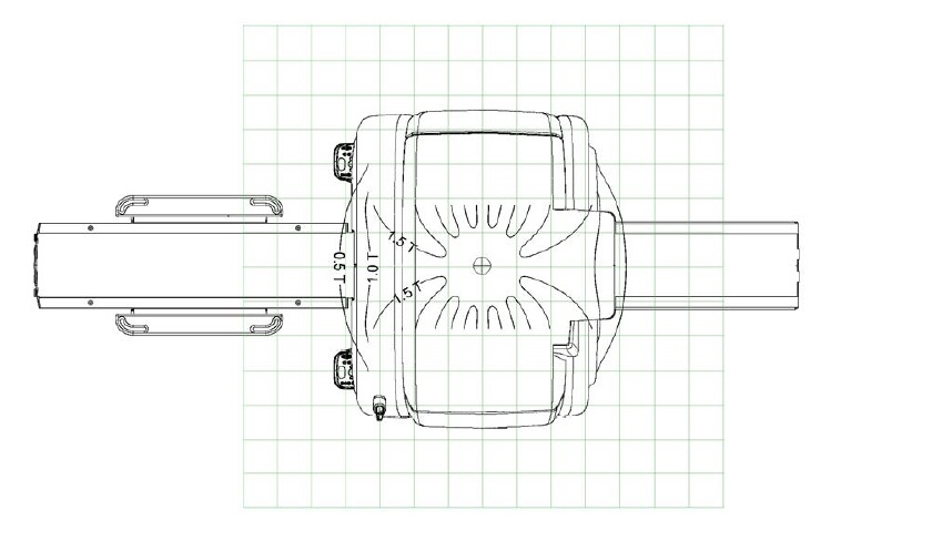
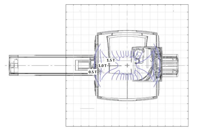
Coordinate system for field and gradient where Z is in the B0 direction, R is the radius, and the origin is isocenter.
The following figures represent the contour map for the static magnetic field (B0) from the MR system at positions accessible to the MR worker.